
Interferometric optical component analyzer based on orthogonal filters

an optical component analyzer and optical component technology, applied in the field of optical network analysis, can solve the problems of limiting the accuracy of measurement, requiring a long measurement time to obtain an accurate technique, and the frequency sweep of a continuously tunable laser source is not uniform

Inactive Publication Date: 2003-03-20
AGILENT TECH INC
View PDF12 Cites 7 Cited by
  • Summary
  • Abstract
  • Description
  • Claims
  • Application Information

AI Technical Summary

Problems solved by technology

A concern with this technique is that the group delay measurement is indirect and limits the accuracy of the measurement.
In addition, the technique requires a long measurement time to obtain an accurate result.
A concern with the interferometric methods using Fourier analysis is that the frequency sweep of a continuously tunable laser source is non-uniform.
The non-uniformity of the frequency sweep causes a similar non-uniformity in the resulting beat frequency that introduces an uncertainty in the calculation of the optical characteristics by means of the Fourier analysis.

Method used


Image

  • Interferometric optical component analyzer based on orthogonal filters
  • Interferometric optical component analyzer based on orthogonal filters
  • Interferometric optical component analyzer based on orthogonal filters

Examples


Embodiment Construction

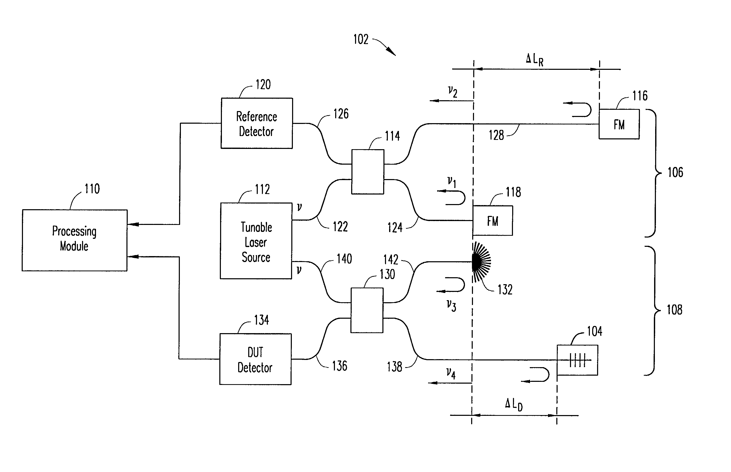
[0032] Tunable laser sources as presently available frequency sweep in a non-uniform manner. A heterodyne beat signal having a beat frequency produced by an interferometer for measuring optical components is affected by the sweep non-uniformity of the tunable laser source. Typical variations of the heterodyne beat signal due to the sweep non-uniformity are substantially larger than those induced by the measured dispersion of the optical component. In characterizing optical components, typical optical measurement systems or optical network analyzers include two interferometers, a non-dispersive reference interferometer and a test interferometer that includes the optical component or device under test (DUT) being measured. The reference interferometer is used for measuring the non-uniform sweep of the tunable laser source, where the measurement of the non-uniform sweep is utilized for compensation of the measurement from the test interferometer. Heterodyne beat signals from both inter...


PUM


Abstract

A system and method for measuring optical characteristics of an optical device under test (DUT) is provided. The system includes a light source for generating an optical signal applied to the optical DUT. A reference interferometer and a test interferometer are optically coupled to the light source. A computing unit is coupled to the interferometers, and utilizes amplitude and phase computing components, such as orthogonal filters, in determining optical characteristics of the optical DUT.

Description

[0001] 1. Field of the Invention[0002] The principles of the present invention relate generally to the field of optical network analysis, and more particularly, to a system and method for determining the optical characteristics of an optical component under test.[0003] 2. Description of Related Art[0004] An optical network analyzer is a vital tool for determining optical characteristics of optical components, such as fiber Bragg gratings. The optical characteristics determined by an optical network analyzer may include reflectance and transmittance of a particular two port or multiport optical component under test. The optical characteristics (e.g., reflection or transmission) of an optical component under test are described by a transfer function and are typically determined by measuring the amplitude and phase of optical signals that have been reflected by or transmitted through the component. The phase response characteristics of an optical component under test are often describe...

Claims


Application Information

Patent Timeline
Patent Type & Authority Applications(United States)
IPC IPC(8): G01B9/02G01J9/04G01M11/00G01M11/02
CPCG01M11/3172G01B2290/60
Inventor SZAFRANIEC, BOGDANVANWIGGEREN, GREGORY D.MOTAMEDI, ALI
Owner AGILENT TECH INC
Learn More