Cable channel assembly

Inactive Publication Date: 2003-03-20
FIBER MANAGEMENT SOLUTIONS
View PDF0 Cites 24 Cited by
  • Summary
  • Abstract
  • Description
  • Claims
  • Application Information

AI Technical Summary

Benefits of technology

[0008] It is another object of the invention to provide a cable channel which provides exit ports with radius protection for the cables carried in the channel.
[0065] As is apparent from the foregoing, the cable raceway outlet 100 can easily be attached to the raceway "R" by placing the raceway outlet 100 over a side wall of the raceway "R" with the clamping members 112 on the inside of the raceway side wall and the latching members 113 on the outside in the open position. With the top edge of the raceway side wall against the top of the bracket assembly 101, the latching members 103 are moved to the position shown in FIG. 13.

Problems solved by technology

Fiber optic cables are susceptible to damage if bent or crimped beyond a certain point.

Method used


Image

  • Cable channel assembly
  • Cable channel assembly
  • Cable channel assembly

Examples


Embodiment Construction

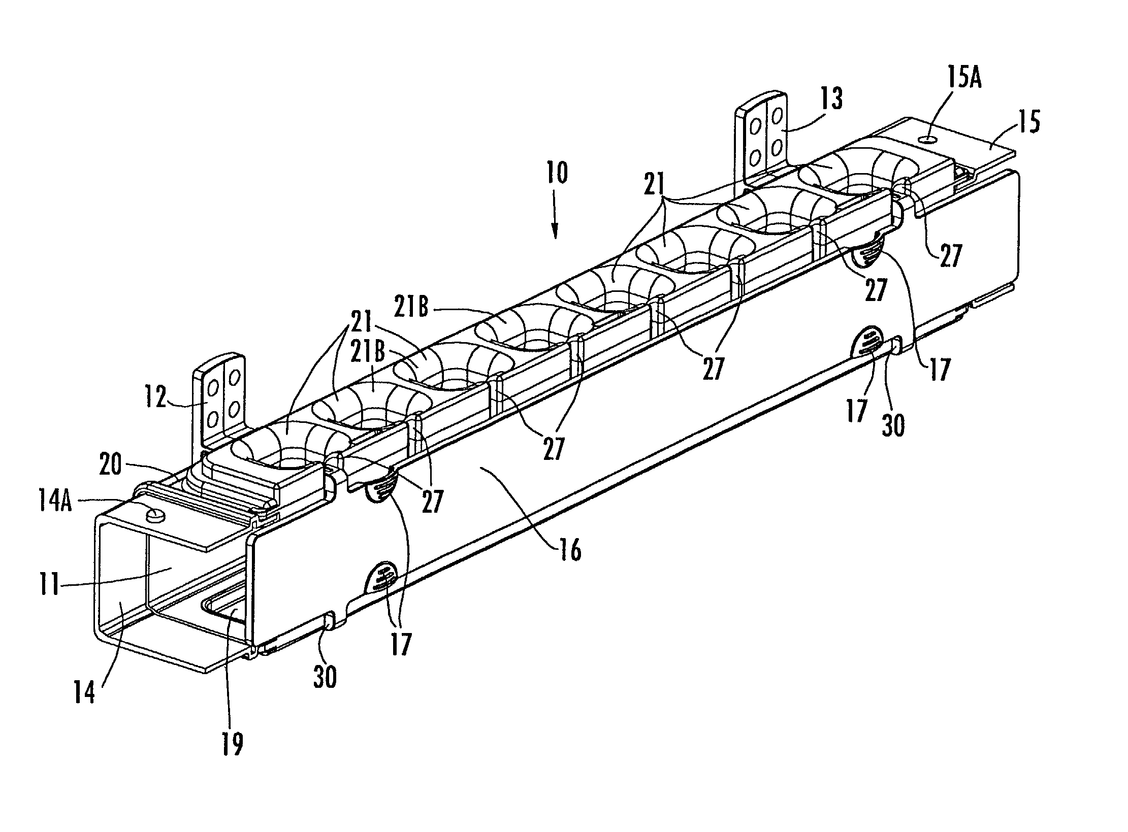
[0047] Referring now specifically to the drawings, a cable channel assembly according to the present invention is illustrated in FIG. 1 and shown generally at reference numeral 10. Ordinarily the cable channel assembly 10 will be used to house cables, such as fiber optic cables, which are being transitioned from a cable raceway, as described in further detail below. In general, the cable channel assembly 10 and its parts are modular and made to snap together and apart without tools. Mounting is accomplished without intrusion of fasteners or fastener elements into the units. The elements are formed of a suitable plastic material, and can be molded by any suitable process. The cable channel assembly 10 can be described in a number of ways, for example, as a "cable manager", or as a "vertical drop." In general, the cable channel assembly 10 is used to "drop" cables in an organized, controlled manner from an overhead horizontal raceway vertically to equipment which the cables interconne...


PUM


Abstract

A cable channel assembly for transitioning cables between first and second planes, and comprising a cable channel segment for being attached in a first plane orientation to a cable raceway positioned a second plane orientation in cable communication therewith for permitting cables to pass between the cable raceway and the attached cable channel segment, and at least one cable exit port extending through a first longitudinally-extending wall of the cable channel segment and adapted to permit the cables to exit the cable channel segment. The cable exit port includes radiused cable-supporting surfaces extending around the periphery of both an interior and exterior side of the first longitudinally-extending wall whereby the cable is supported on a radius on the interior of and exterior to the cable channel segment as the cable exits the cable channel segment.

Description

TECHNICAL FIELD AND BACKGROUND OF THE INVENTION[0001] This invention relates to a cable channel assembly, and a cable channel assembly and raceway outlet combination which have particular application in the operation of fiber optic cable telecommunication systems. These systems can also be used in any system where it is necessary to route flexible cables of any type. Fiber optic cable management often requires that fiber optic cables be routed between fiber optic distribution equipment and, for example, fiber optic line terminating equipment in buildings and other structures. Fiber optic cables are susceptible to damage if bent or crimped beyond a certain point. Standards have evolved which govern the degree of bend radius permitted in fiber optic cables of specified sizes.[0002] Fiber optic cables are thus routed along raceways which are designed to protect the cable from damage while permitting access for modification, maintenance, connection and repair. These raceways are typical...

Claims


Application Information

Patent Timeline
IPC IPC(8): H02G3/04
CPCH02G3/045
Inventor MATTEI, MICHAELAUTERI, ROBERT P.
Owner FIBER MANAGEMENT SOLUTIONS
Why Eureka
Try Eureka