Aerial video mount

Inactive Publication Date: 2010-02-09
MOILANEN JOE A
View PDF19 Cites 19 Cited by
  • Summary
  • Abstract
  • Description
  • Claims
  • Application Information

AI Technical Summary

Benefits of technology

[0002]The present invention is a stabilizing and vibration-isolating mount to facilitate the manual operation of a camera from mobile platforms such as aircraft, motor vehicles, and watercraft. The mount comprises a carriage assembly comprising a carriage that rolls on top of a set of curved carriage rails. This assembly allows the roll axis of rotation to pass through the optical axis of the camera lens, thus eliminating the pendulum or over-the-center phenomenon that characterizes moving images filmed while the camera is moving about the roll axis. The mount permits rotation of the camera about the tilt axis by a pivotal bearing that is adjustably attached to the upper end of a yoke. The bottom of the yoke comprises a stud which passes through a bearing on a hub plate and thus allows the yoke to pivot around the pan axis. Movement about all three axes of rotation can be stabilized by gyrostabilizers that can be adjustably positioned through the center lines of the respective axes.
[0003]The mount utilizes vibration isolators mounted between the seat plate and another supporting plate. The isolators reduce the transmission of vibrations from the aircraft, vehicle, or watercraft to the rest of the mount. The reduction in the transmitted vibrations improves the quality of the images produced by the camera by largely eliminating the adverse effect caused by vibration. In addition, the reduction of transmitted vibration facilitates the operation of the camera by making it easier to observe the viewfinder or viewing screen of the camera, as well as reducing the impediment that high levels of vibration cause to the smooth movement of the camera.
[0004]Setting up and operating the mount is straightforward. The camera is attached to the camera base plate which is thereafter adjusted so that the optical axis of the lens is centered into alignment with the roll axis of the mount. This adjustment can be facilitated by a removable centering guide that temporarily placed into a slot adjacent to the carriage rails. Gyrostabilizers can be likewise attached to their respective base plates and adjusted so that they are properly centered and aligned with the appropriate axis of rotation. Further adjustments to the balance, center of gravity, and total height of the camera can be made by moving and securing weights at various places on the mount and by moving and securing adjustable rails and plates.
[0005]In the preferred embodiment, the mount comprises a seat base with latches that allows the mount to be secured and quickly removed from the seat boxes of certain kinds of aircraft. This renders the mount portable but also permits the mount to be securely affixed to an aircraft without having to obtain a supplemental type certification from the Federal Aviation Administration. Other modes of attachment, such with straps, clamps, and bolts can also be used to removably secure the mount to an aircraft, vehicle, or watercraft. Once the mount is attached, the operator can adjust pan stops if desired to limit the rotation about the pan axis so as to avoid filming extraneous visual elements such as the door frame of an aircraft.
[0006]Once the gyrostabilizers are activated and allowed to reach their operating rate of rotation, they exert a stabilizing effect along each axis of rotation and thus restrain the camera from jostling or other inadvertent motion. However, the camera operator can overcome the resistance to movement by smoothly directing the camera into the desired position. In the preferred embodiment, the carriage is fitted with grips that allow the operator to direct the camera without touching the camera.

Problems solved by technology

One of the recurring problems in photographing or filming from aircraft, motor vehicles, and watercraft is that the jostling and vibration of the camera can mar the visual quality of the images or footage.
This problem is particularly difficult to resolve when filming from helicopters because of the very high level of vibration.

Method used


Image

  • Aerial video mount
  • Aerial video mount
  • Aerial video mount

Examples


Embodiment Construction

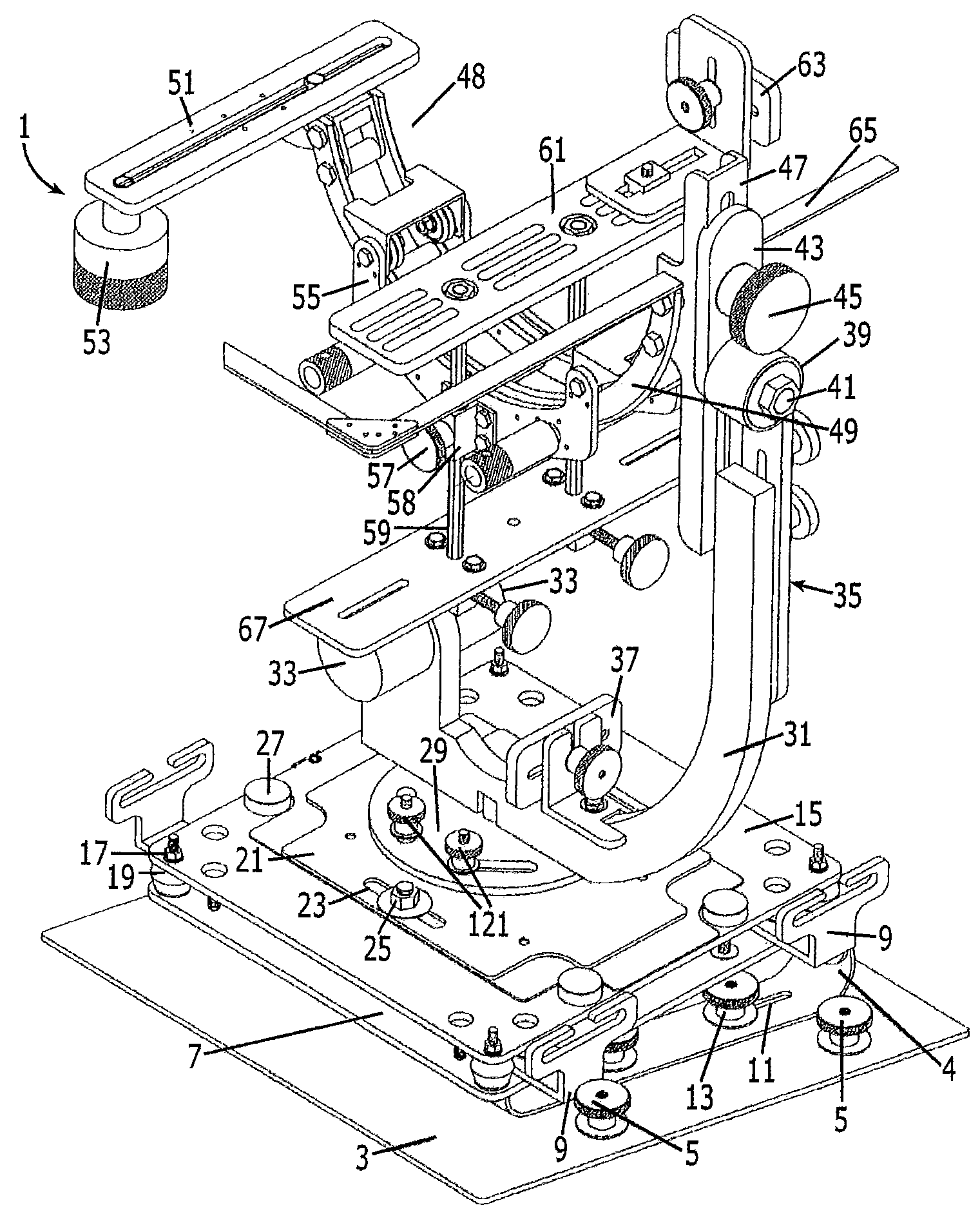
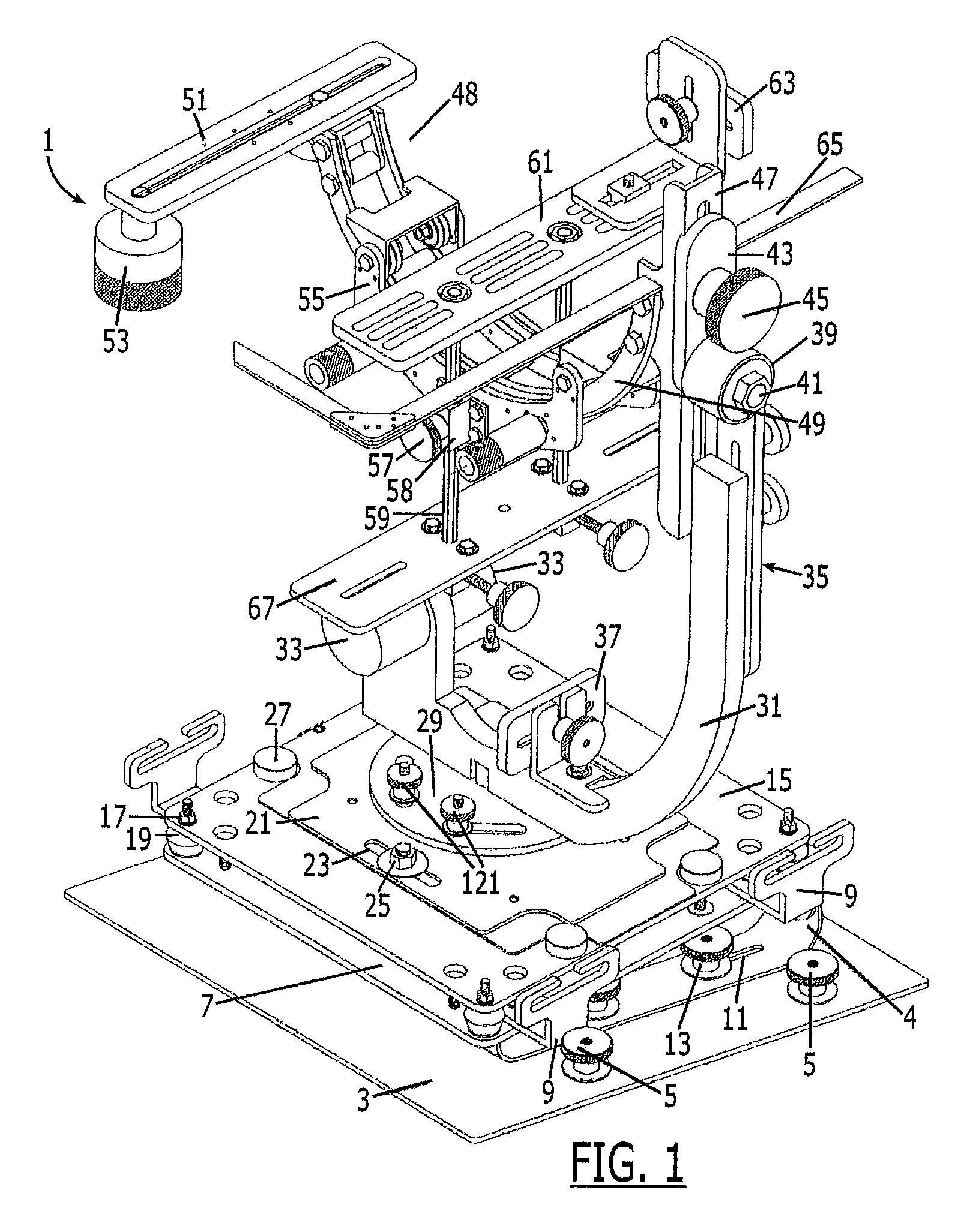
[0017]As shown in FIG. 1, the preferred embodiment of the mount 1 comprises a seat plate 3 to which are attached latch knobs 5 used to secure the seat plate 3 to the seat of a vehicle or aircraft enabled to accept the latching mechanism. The seat plate 3 supports the center plate 7 to which tie down brackets 9 are attached to enable the mount 1 to be attached to a seat using straps such as a seat belts. The position of the center plate 7 can be adjusted relative to the seat plate 3 by an arrangement of slots 11 and lock knobs 13. One end of the center plate 7 can also be elevated with respect to the seat plate 3 by an adjustable level support 4. The base plate 15 is attached to the center plate 7 by fasteners 17 which are attached to vibration isolators 19. The purpose of the vibration isolators 19 is to reduce vibration transmitted from the aircraft or vehicle to the base plate 15 and components resting on the base plate. The vibration isolators can be made of various material incl...


PUM


Abstract

A stabilizing and vibration-isolating mount to facilitate the manual operation of a camera from mobile platforms such as aircraft, motor vehicles, and watercraft. The camera mount comprises a carriage assembly that allows the roll axis of rotation to pass through the optical axis of the camera lens, thus eliminating the pendulum or over-the-center phenomenon that characterizes moving images filmed while the camera is moving about the roll axis. Movement around all three axes of rotation can be stabilized by gyrostabilizers that can be adjustably positioned through the centerlines of the pan, roll, and tilt axes.

Description

BACKGROUND OF THE INVENTION[0001]The use of video and motion picture cameras in aircraft and other moving vehicles is well known in applications such as news coverage, movie production, and aerial reconnaissance. One of the recurring problems in photographing or filming from aircraft, motor vehicles, and watercraft is that the jostling and vibration of the camera can mar the visual quality of the images or footage. This problem is particularly difficult to resolve when filming from helicopters because of the very high level of vibration. Much of the video and motion picture photography that is done from aircraft uses mounts that are integrally attached to the aircraft and therefore require structural modification of the aircraft and certification by the Federal Aviation Administration. What is needed for many applications is a mount that stabilizes the camera and reduces the level of vibration transmitted by the aircraft, vehicle, or watercraft.SUMMARY OF THE INVENTION[0002]The pres...

Claims


Application Information

Patent Timeline
IPC IPC(8): H04N5/225G01C19/02G03B17/00
CPCG01C21/18G03B17/00Y10T74/1221
Inventor MOILANEN, JOE A.
Owner MOILANEN JOE A
Why Eureka
Try Eureka