Turbogroup of a power generating plant

a technology of power generating plant and turbine unit, which is applied in the direction of gas turbine plant, hot gas positive displacement engine plant, machine/engine, etc., can solve the problems of friction, heat generation, wear, and increase in temperature differences in the outer casing of the turbine unit from top to bottom, and the relative position between

Inactive Publication Date: 2003-02-20
ANSALDO ENERGIA SWITZERLAND AG
View PDF9 Cites 10 Cited by
  • Summary
  • Abstract
  • Description
  • Claims
  • Application Information

AI Technical Summary

Problems solved by technology

Thrust bearings react in a sensitive manner to changes in inclination and misalignments; in particular, friction, the generation of heat, and wear increase.
However, if a combustion chamber lying at the top, a "silo combustion chamber", is used instead of an annular combustion chamber, temperature differences in the outer casing of the turbine unit from top to bottom cannot be ruled out.
Since the thrust-bearing unit is normally integrated in the casing of the turbine unit next to the second radial bearing unit, the relative position between the bearing axis of the bearing unit fixed to the casing and ...

Method used


Image

  • Turbogroup of a power generating plant
  • Turbogroup of a power generating plant
  • Turbogroup of a power generating plant

Examples


Embodiment Construction

[0007] The invention is intended to provide a remedy here. The invention, as characterized in the claims, deals with the problem of showing how, for a turbogroup of the type mentioned at the beginning, to make it possible or easier to influence the vibration behavior of the turbine unit and / or of the bearing system.

[0008] This problem is achieved according to the invention by the subject matter of the independent claim. Advantageous embodiments are the subject matter of the dependent claims.

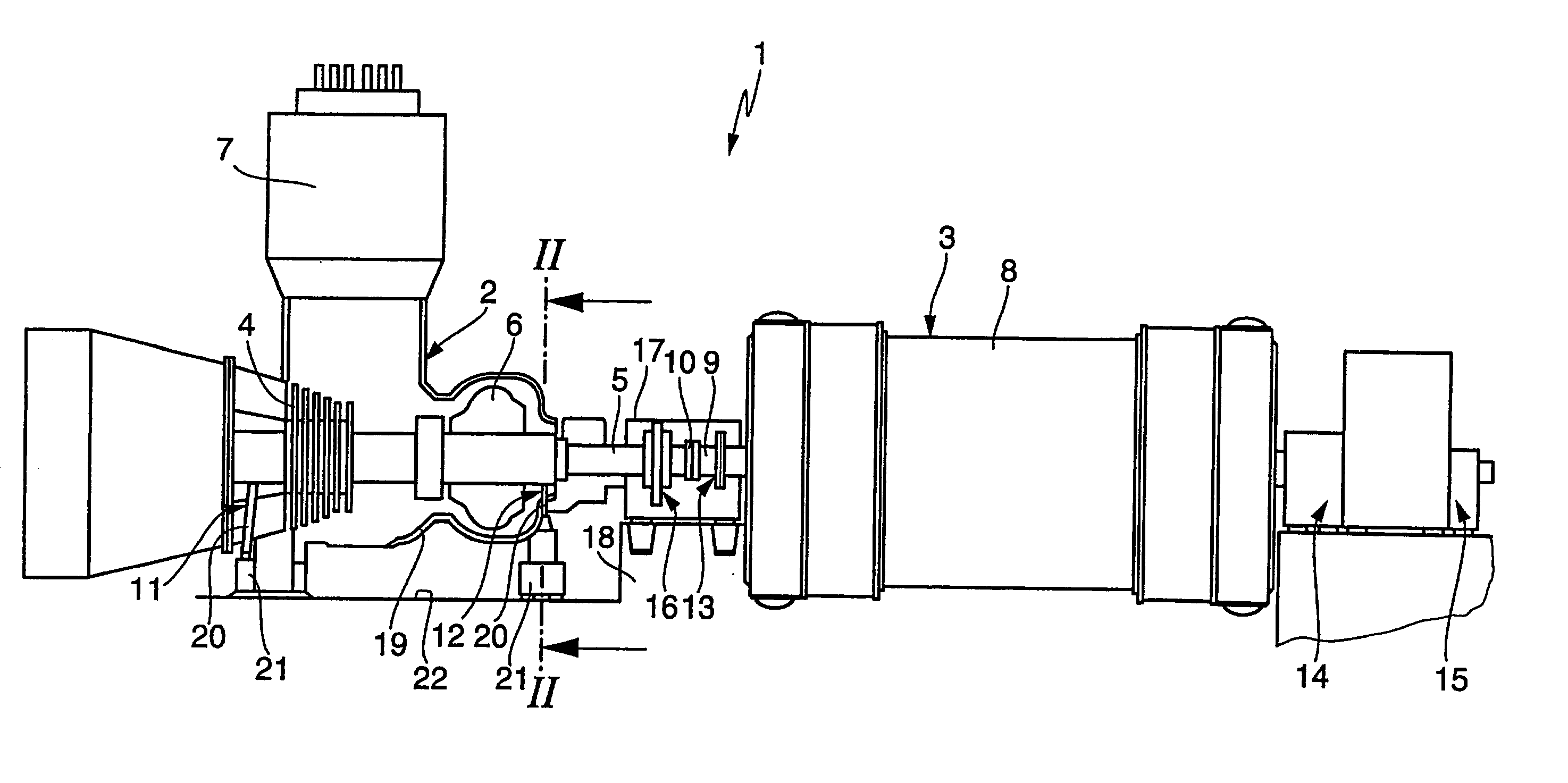
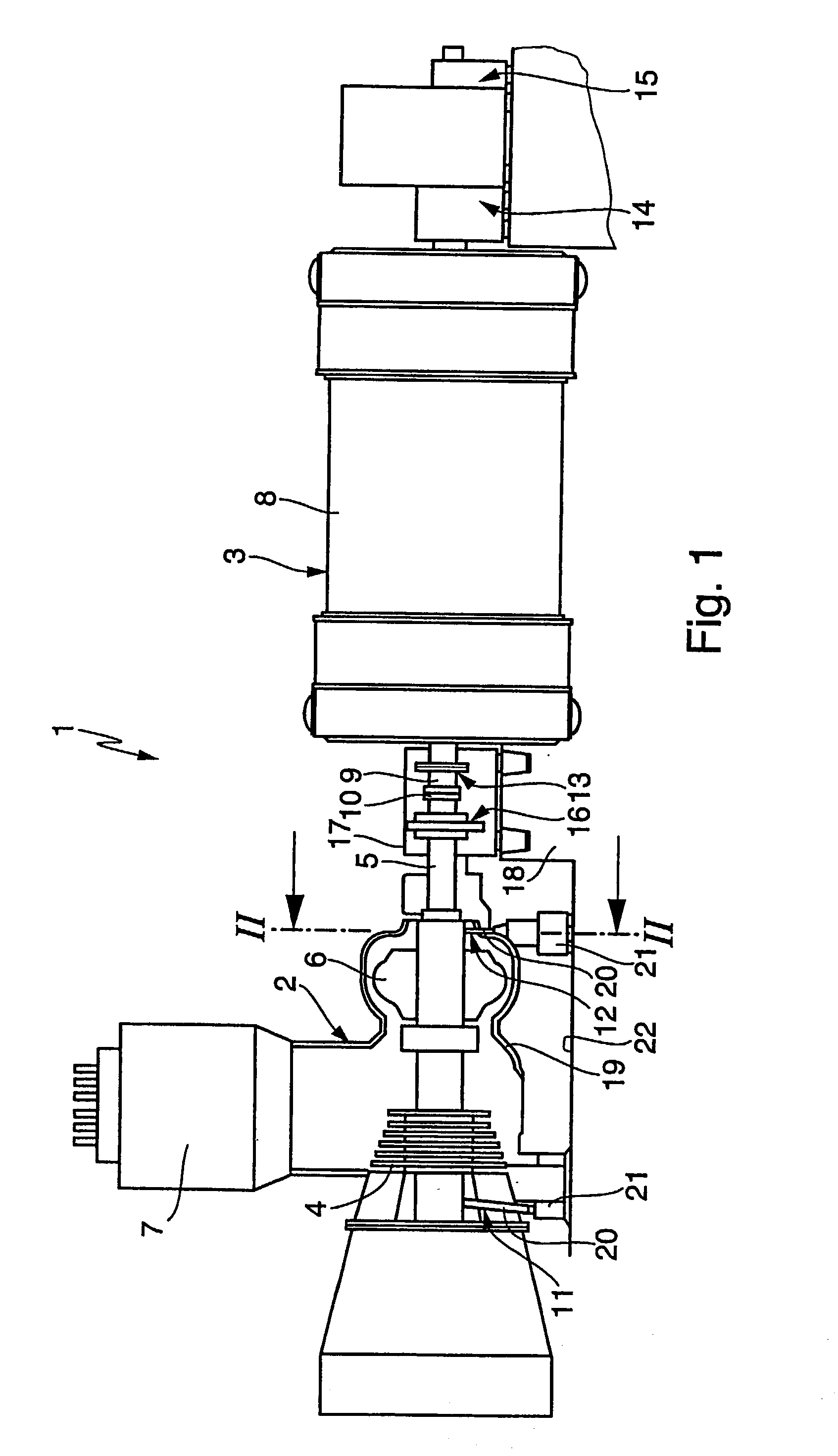
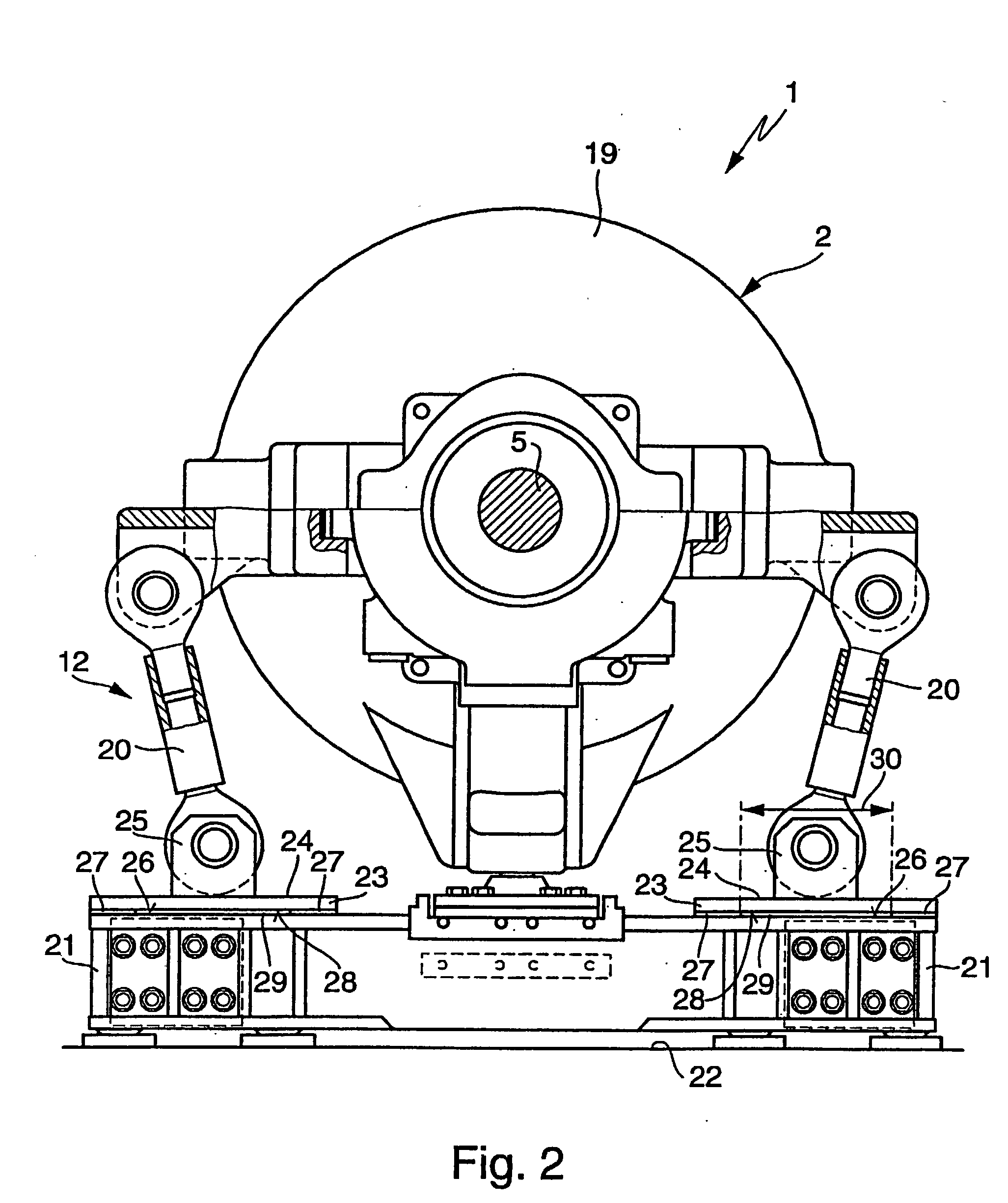
[0009] In the inventive embodiment of the turbogroup, the first radial bearing unit and / or the second radial bearing unit have pendulum supports which are in each case supported on a bearing pedestal. The present invention is now based on the general idea of supporting the pendulum supports, at least at one radial bearing unit of the turbine unit, on the associated bearing pedestal in each case via a spring element. Such a spring element changes the vibration properties of the respective radial b...


PUM


Abstract

The present invention relates to a turbogroup (1) of a power generating plant. A turbine unit (2), has a turbine (4) and a further fluid-flow machine (6) on a common turbine shaft. A generator unit (3), has a generator (8) on a generator shaft (9). The turbine shaft (5) and the generator shaft (9) are connected to one another. A third radial bearing unit (13) supports the generator shaft (9) on a side of the generator (8) which faces the turbine unit (2). A thrust bearing unit (16) supports the turbine shaft (5) axially between the generator (8) and the additional fluid-flow machine (6). A first radial bearing unit (11) and/or a second radial bearing unit (12) have/has pendulum supports (20) which are in each case supported on a bearing pedestal (21). At least one of the pendulum supports (20) is supported on the associated bearing pedestal (21) via a spring element.

Description

[0001] The invention relates to a turbogroup of a power generating plant, in particular a gas-storage power plant, comprising a turbine unit and a generator unit.PRIOR ART[0002] A turbine unit normally has a turbine and a further fluid-flow machine on a common turbine shaft. In a conventional power generating plant, this further fluid-flow machine may be formed by a compressor which is driven by the turbine via the turbine shaft. In a gas-storage power plant, in particular an air-storage power plant, this further fluid-flow machine is formed by an additional turbine, to which the gas of a gas reservoir of the gas-storage power plant is admitted, so that the additional turbine likewise transmits drive output to the turbine shaft. As a rule, a generator unit has a rotor of a generator on a generator shaft and serves to generate electricity. The turbine unit serves to drive the generator unit, so that accordingly the turbine shaft is in drive connection with the generator shaft.[0003] ...

Claims


Application Information

Patent Timeline
IPC IPC(8): F01D25/16
CPCF01D25/164
Inventor HUSTER, JOSEFKELLER, SUSANNELOBMUELLER, WALTER
Owner ANSALDO ENERGIA SWITZERLAND AG
Why Eureka
Try Eureka