
Device for connecting and blocking hollow elements for the formation of fluid distribution plants

a technology of fluid distribution plant and hollow element, which is applied in the direction of rod connection, washing machine, manufacturing tool, etc., can solve the problems of insufficient reliability of large sections of piping, jeopardizing the connection between the various components, and consequently the efficiency and safety of the plan

Active Publication Date: 2003-01-23
TESEO SRL
View PDF7 Cites 10 Cited by
  • Summary
  • Abstract
  • Description
  • Claims
  • Application Information

AI Technical Summary

Benefits of technology

[0008] One object of the present invention is to provide and achieve means which fully ensure a static and reliable coupling of hollow bars or section pipes for piping fluids, including piping with large diameters and where operating pressures are very high.
[0009] Another object of the present invention is to provide coupling devices able to achieve anchoring of the elements to be connected, not only due to anchoring by screws, but above all due to a physical connection and gripping between at least one of the coupling systems and at least one surface of the connected elements.

Problems solved by technology

A similar method of connecting the piping bars is efficient and practical, but may result in not being sufficiently reliable for large sections of piping and where high delivery pressures are used, that is when the thrust which tends to force apart the joined parts is very high.
In this case in fact, the thrust in play may cause the plugs or anchoring plates to slide in their grooves and the connecting plates to slide on the external surface of the bars, thus jeopardizing the connection between the various components and consequently the efficiency and safety of the plant.

Method used


Image

  • Device for connecting and blocking hollow elements for the formation of fluid distribution plants
  • Device for connecting and blocking hollow elements for the formation of fluid distribution plants
  • Device for connecting and blocking hollow elements for the formation of fluid distribution plants

Examples


Embodiment Construction

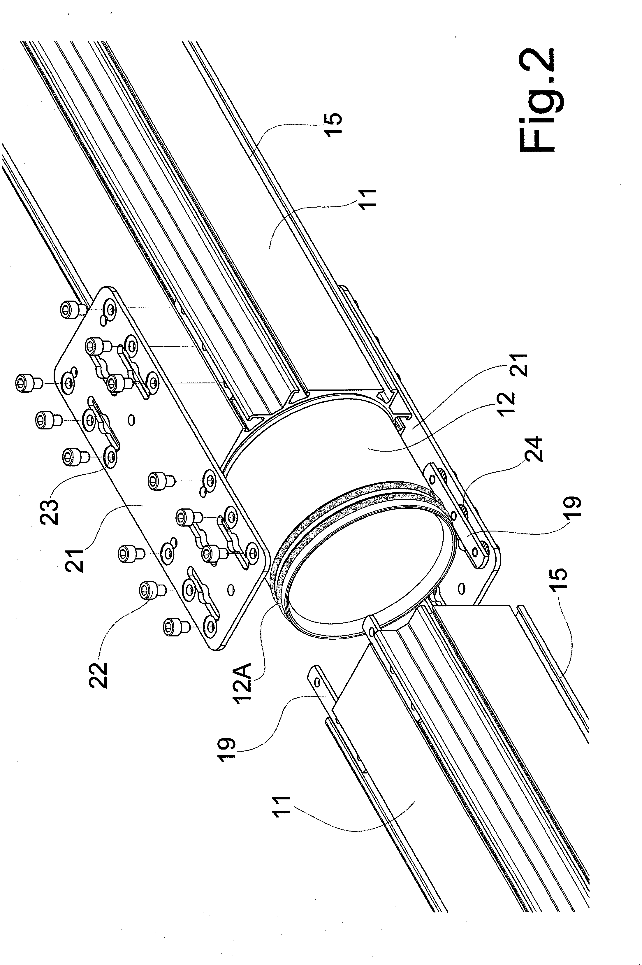
[0024] In said drawings, 11 indicates a hollow bar is indicated which is connectable to another identical hollow bar through an interposed tubular connection 12 or directly by an end piece or an additional end fitting 13.

[0025] Each hollow bar 11, which can also be called a pipe section, has a four-sided section and is extruded aluminium or one of its alloys. It has, as it is well known, a central hole 14, and, along its walls, C shaped, outward facing, channels 15.

[0026] The end element or fitting 13, which may have a through or blind central hole and / or at least one internal or external threaded zone 16 as in the example in FIGS. 4 to 6, is, in preference, made using a four-sided external walls profile identical to the hollow bar one or section pipe 11, which has, therefore, with longitudinal channel shaped grooves 17, and an end cylindrical section 18 to fit into the hole 14 of the hollow bar 11 to which it is to be connected.

[0027] The union between the two bars or identical sec...


PUM

PropertyMeasurementUnit
areaaaaaaaaaaa
pressureaaaaaaaaaa
diametersaaaaaaaaaa

Abstract

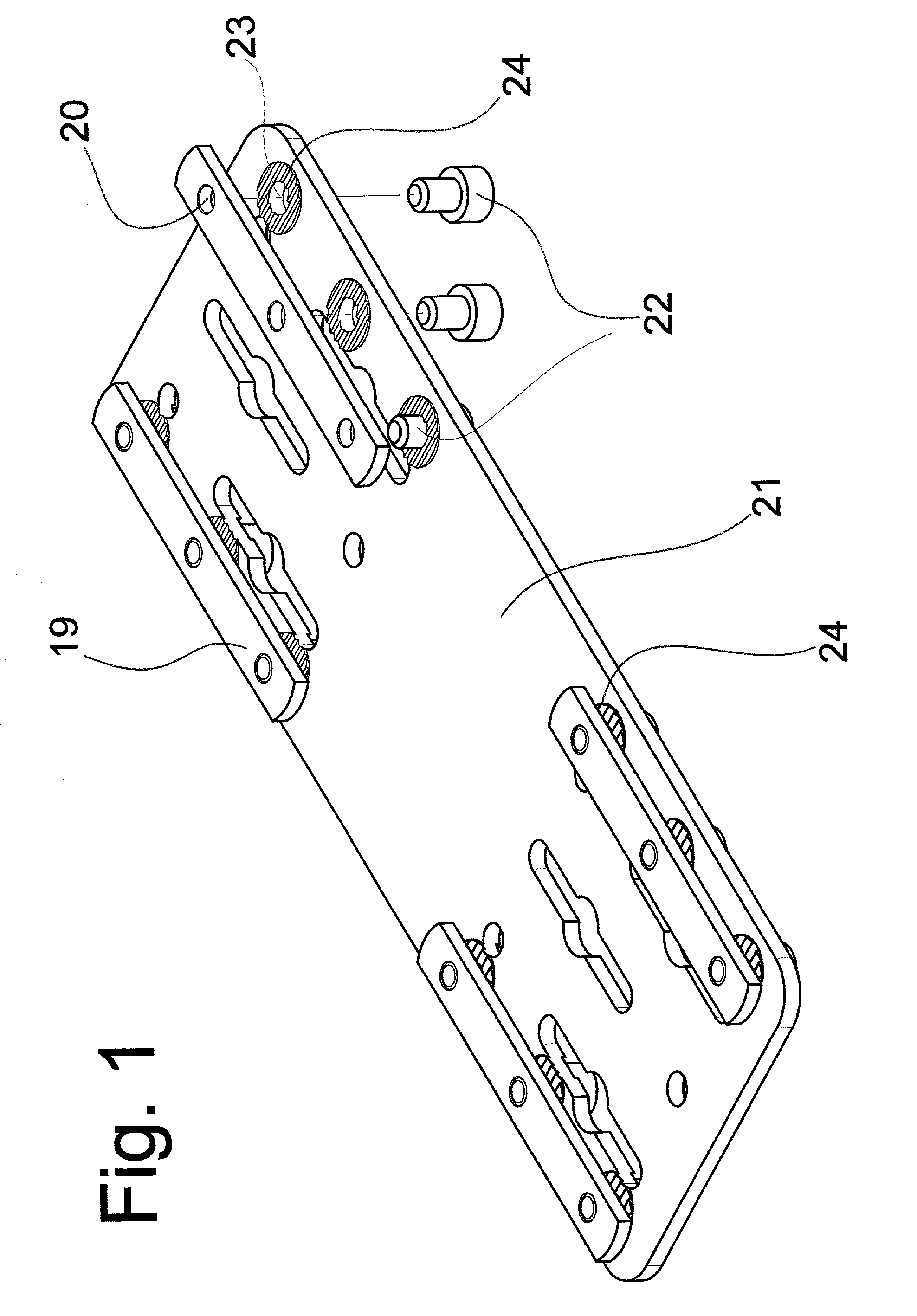
The invention relates to a device for connecting and blocking hollow elements used as piping for fluids, both gaseous and liquids, The hollow elements (11,13) are connectable by plugs or anchoring plates (19) and connecting plate (21), engaging at least one wall of adjacent elements and fixed by anchoring screws (22). At least the connecting plate (21) is provided with protrusions or contact grips (24) designed to physically penetrate into the surface of the elements to be connected when the connecting plate is anchored to the anchoring plate by the screws.

Description

[0001] The present invention concerns plants for piping fluids, both gaseous and liquids, under pressure or under vacuum and is aimed in particular at an innovative system of linear, angular, T or cross connections of hollow elements, such as hollow bars, relative fittings and accessories for the formation of such plants.STATE OF THE TECHNIQUE[0002] The achievement and use, as piping, of hollow bars or section pipes, consecutively connectable to form canalisation and distribution plants for fluids in general are well known.[0003] Each hollow bar for such an use is usually made up of an extruded aluminium or aluminium alloy square section. Fundamentally, it has a central longitudinal hole and, along the external walls, C shaped grooves, also longitudinal, opening outwards. The channel shaped grooves are delimited by ribbing or finning achieved by extrusion and are used to anchor the fastenings used to join the hollow bars together and / or supplementary elements to the ends of the asse...

Claims


Application Information

Patent Timeline
Patent Type & Authority Applications(United States)
IPC IPC(8): F16B7/04F16B7/18F16L21/00F16B43/00F16L21/02F16L25/08
CPCY10T29/49947F16L25/08
Inventor GUZZONI, PAOLO
Owner TESEO SRL
Learn More