Fastening device with tolerance compensation

Active Publication Date: 2012-11-01
BOLLHOFF VERBINDUNGSTECHNIK GMBH
View PDF7 Cites 6 Cited by
  • Summary
  • Abstract
  • Description
  • Claims
  • Application Information

AI Technical Summary

Benefits of technology

[0009]The inventive fastening device provides a design which is less space consuming than the state of the art, which inventive device is distinguished by smooth and easy installation, and effective tolerance compensation. The connection of the holding element and the adjusting element via an external thread of the holding element provides a compact arrangement. The special carrying element design based on a spring-loaded ring with a carrying or dragging element thread and a carrying element thread blocking means provides reliable rotational carrying of the adjusting element with the rotational movement of the fastening screw. The carrying element thread guarantees that the fastening screw cannot be pressed through the carrying element. Further, the carrying element provides a reliable coupling to the fastening screw, so that after the carrying element thread enters into the thread of the fastening screw, immediately a rotational movement of the fastening screw is transmitted to the adjusting element, to achieve effective tolerance compensation. In addition, the combination of the carrying element thread and the carrying element thread blocking means in the carrying element serves to prevent high friction forces from impeding (or making more difficult) the rotation of the fastening screw into the carrying element, and in this way lengthening the time of installation of the fastening device.
[0015]According to another embodiment of the invention, the carrying element thread blocking means of the carrying element is comprised of a radially inwardly extending detent or cam. Another alternative form for the carrying element thread blocking means comprises an axially extending projection, which blocks the carrying element thread against further rotational penetration by the fastening screw. Both the radially inwardly extending detent and the axially extending projection are radially outwardly irreversibly deformable or radially outwardly displaceable, so that when a torque threshold is exceeded the carrying element thread blocking means can be overcome with the aid of the fastening screw, so that the fastening screw will be capable of being screwed-in further. The detent (or the projection) is preferably disposed close to the outlet of the carrying element thread.
[0016]According to yet another preferred embodiment of the fastening device, the holding element has at least one latch recess on an end face facing the carrying element, so that the adjusting element is releasably blocked against rotation, via a circularly arcuate or tangentially extending spring-loaded arm with a latch projection, on the fastening ring, or an axial latch projection on the spring-loaded ring. With this arrangement, transport security for the fastening device is provided.

Problems solved by technology

In addition to the carrying or dragging element itself, the tolerance compensating element has a space-consuming design in both the radial and the axial direction, so that a correspondingly large space in the installation between the two components must be provided for.
This fastening device also requires a large accommodation space both in the radial and the axial direction, so that it is disadvantageous in a situation where economy of space is needed.
Also, the fastening screw must fully pass through the plastic bushing during installation, which increases the time needed for installation of the fastening device, due to the increased torque.
If the plastic bushing is dimensioned too short or too soft, the fastening screw may be passed through in a disadvantageous manner.

Method used


Image

  • Fastening device with tolerance compensation
  • Fastening device with tolerance compensation
  • Fastening device with tolerance compensation

Examples


Embodiment Construction

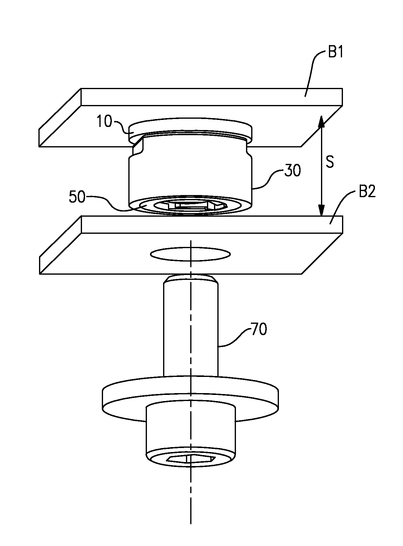
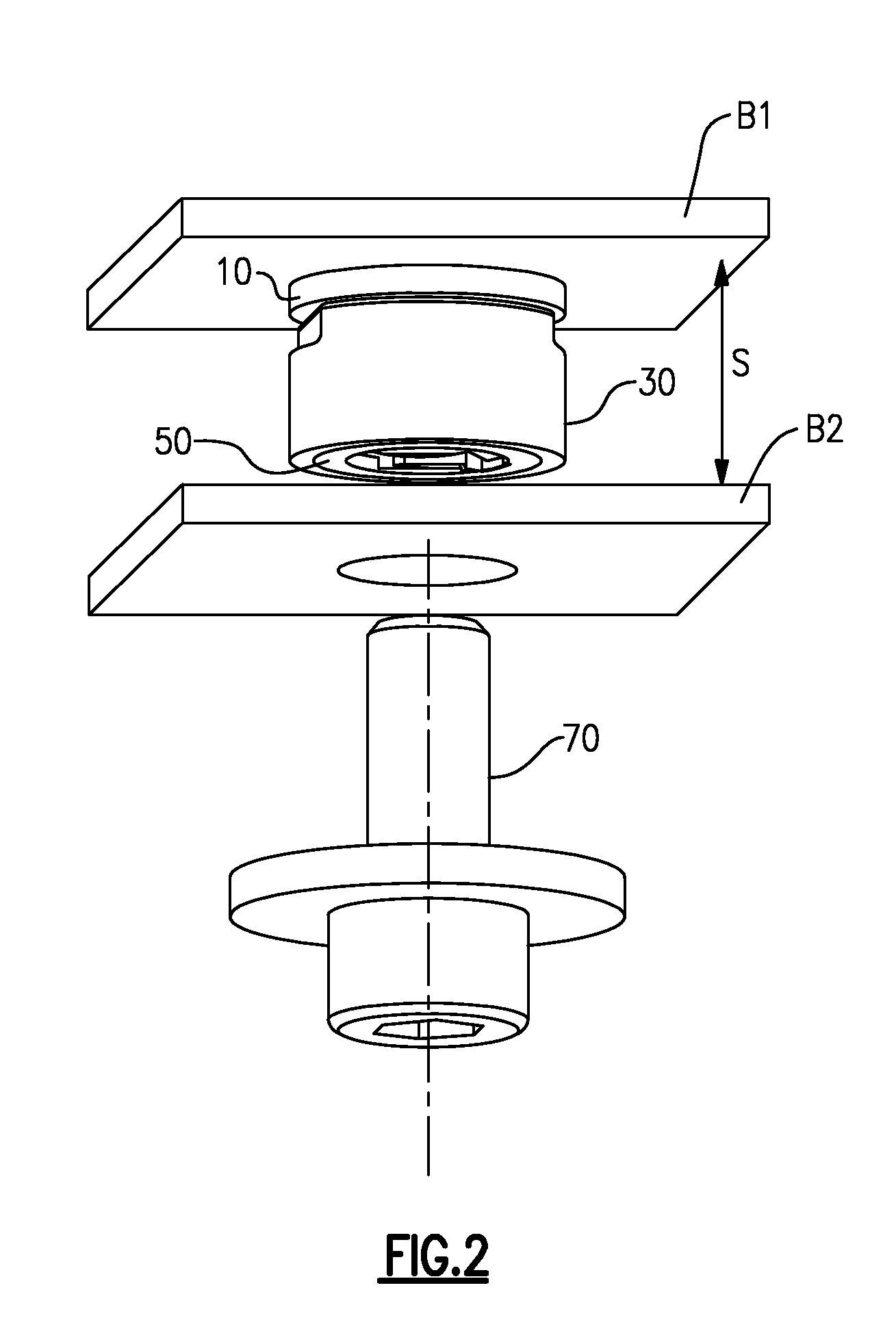
[0040]The fastening device illustrated in FIGS. 10 and 11 serves to fasten a first component B1 to a second component B2. The second component B2 is, for example, a support of a motor vehicle, while the first component B1 is a part of a headlight housing fixed by fixtures. According to a further embodiment, the first component B1 is a guide rail for a sliding roof, which is fastened to the vehicle frame, thus to the second component B2. The first component B1 and the second component B2 are at a distance S apart, which can vary based on tolerances related to mounting and / or fabrication conditions. The fastening device illustrated allows automatic adjustment of these tolerances.

[0041]The fastening device is comprised of a holding element 10, an adjusting element 30, and a fastening screw 70. The holding element 10 and the adjusting element 30 form a pre-assemblable component unit E, as illustrated in an exploded view in FIG. 5.

[0042]The holding element 10 in particular is illustrated...


PUM

PropertyMeasurementUnit
Angleaaaaaaaaaa
Diameteraaaaaaaaaa
Distanceaaaaaaaaaa

Abstract

A fastening device for fastening a first component B1 to a second component B2, with automatic compensation of tolerances in the distance S between the first component B1 and the second component B2. The fastening device includes a holding element and an adjusting element. A carrying element is provided on the adjusting element, the carrying element having a ring which is spring-loaded in the axial direction of the adjusting element, and in which a carrying element includes a carrying element thread and an overcomeable carrying element thread blocking means.

Description

FIELD OF THE INVENTION[0001]The invention relates to a fastening device for fastening a first component to a second component, with automatic compensation of tolerances between these components; further, a component with an installed fastening device; and a method of installation of a fastening device.BACKGROUND OF THE INVENTION[0002]Numerous types of fastening devices with tolerance compensation are known. Typically, these devices comprise an adjusting bushing with a so-called “carrying section” or “dragging section”, which can enter into a friction-locked connection to a fastening screw. When the fastening screw is rotated, the adjusting bushing is then rotated along with it, until the bushing abuts against one of the two components which are disposed a distance apart. When the fastening screw is further rotated, with corresponding increasing of the torque, the friction-locked connection between the fastening screw and the carrying or dragging section is overcome, so that then the...

Claims


Application Information

Patent Timeline
IPC IPC(8): F16B29/00B23P11/00
CPCB62D25/147F16B5/0233Y10T403/75Y10T29/49947Y10T403/335B62D25/08F16B5/02F16B33/00F16B37/04
Inventor FIGGE, HANS-ULRICHKOHLBRENNER, KARL-HEINZKONIG, MICHAEL
Owner BOLLHOFF VERBINDUNGSTECHNIK GMBH
Why Eureka
Try Eureka