
Electric Motor

a technology of electric motors and motors, applied in the direction of dynamo-electric machines, magnetic circuit shapes/forms/construction, supports/enclosements/casings, etc., can solve problems such as irritating noises in passenger compartments

Inactive Publication Date: 2003-01-09
ROBERT BOSCH GMBH
View PDF2 Cites 14 Cited by
  • Summary
  • Abstract
  • Description
  • Claims
  • Application Information

AI Technical Summary

Benefits of technology

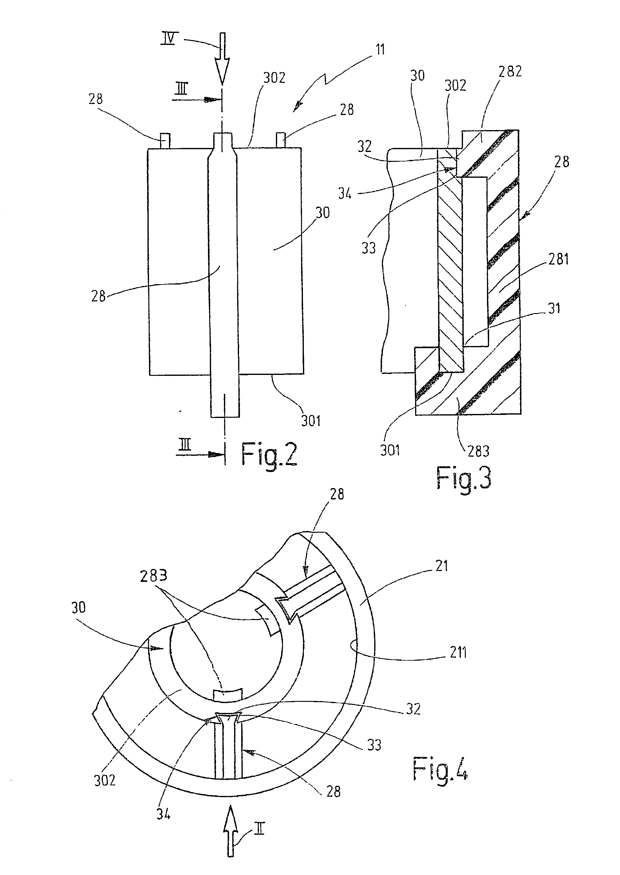
[0005] The electric motor of the invention has the advantage that noise reduction occurs along with a structural simple, sturdy design of the motor. Bearing hoops for the rotor bearings, which are complicated to produce and difficult to install, are dispensed with. The rotor bearings are instead secured rigidly to the housing by their bearing sleeves and can easily be jointly injection-molded in the process of producing the housing by injection molding. The rotor bearings, preferably embodied as slide bearings, cannot transmit tangential forces of the rotor, and they are thus decoupled from the stator. Because of the spring-elastic fastening of the stator to the housing, there is no rigid connection between the stator and the housing, which prevents the transmission of structure-borne sound from the stator to the housing.[0006] By the provisions recited in the further claims, advantageous refinements and improvements to the electric motor defined by claim 1 are possible.[0007] In one advantageous embodiment of the invention, for the spring-elastic suspension of the stator from the housing, decoupling elements, at which the stator is retained by nonpositive and / or positive engagement are secured to the inner wall of a housing pot, spaced apart from one another in the circumferential direction.[0008] In a preferred embodiment of the invention, the decoupling elements comprise an elastomer and, by the two-component process, are jointly injection-molded onto the plastic injection-molded housing.

Problems solved by technology

In such electric motors, 12th- and 24th-order slot-frequency noises occur, which if the electric motor is for instance used as a blower motor in an air conditioner are emitted as airborne and structure-borne sound past the blower housing and cause quite irritating noises in the passenger compartment.

Method used


Image

  • Electric Motor
  • Electric Motor
  • Electric Motor

Examples


Embodiment Construction

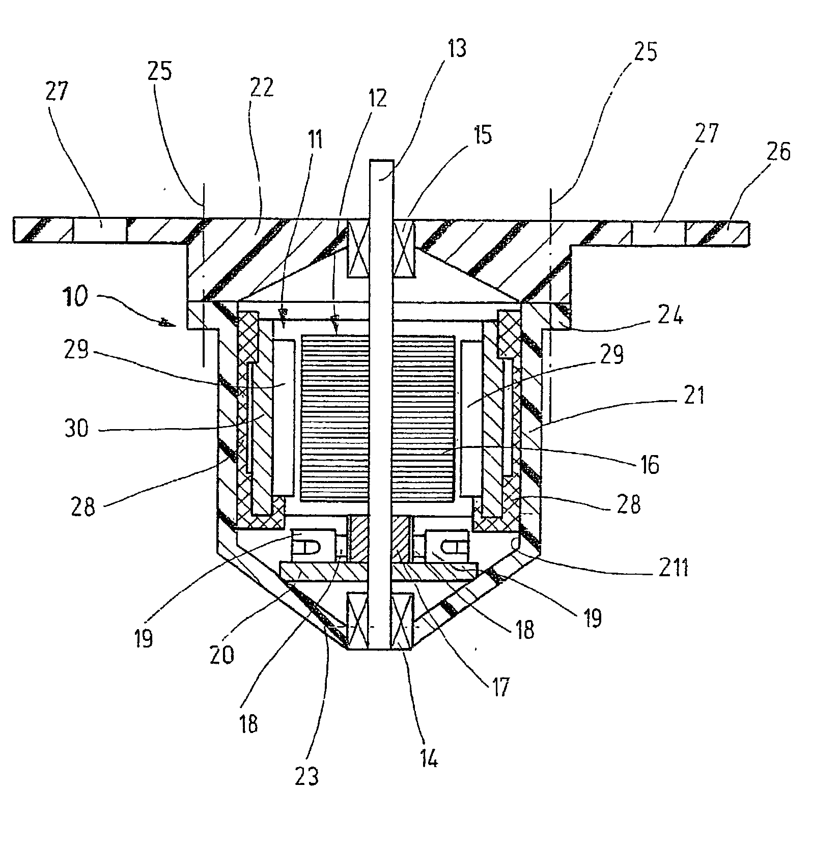
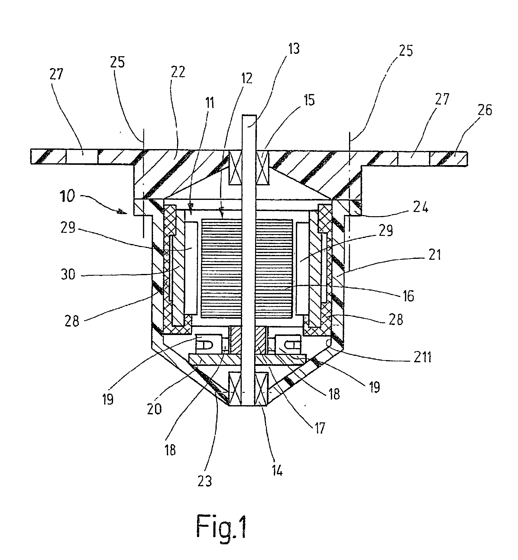
[0014] The electric motor, schematically shown in longitudinal section in FIG. 1 and preferably used in motor vehicles, in particular as a blower motor in air conditioners, is embodied here as a commutator motor as an example and in a known manner has a stator 11 and a rotor 12 that rotates in the stator 11; to that end, with its rotor body 16 which for instance is laminated and is also known as a rotor lamination packet, the rotor is seated in a manner fixed against relative rotation on a rotor shaft 13, which is received in rotor bearings 14, 15 embodied here as slide bearings. A rotor winding, not shown for the sake of simplicity, rests in axial slots of the rotor body 16 and is electrically connected to a current inverter or commutator 17 that is seated on the rotor shaft 13 in a manner fixed against relative rotation. For delivering current to the rotor winding, commutator or carbon brushes 18 are used, which are guided radially displaceably in so-called quivers 19 of a brush h...


PUM


Abstract

In an electric motor with a stator (11) and a rotor (12) that is received rotatably via its rotor shaft (13) in rotor bearings (14, 15), and having an effective decoupling between the stator (11) and rotor bearings (14, 15) for reducing the emission of airborne and structure-borne sound, in order to attain a structurally simple, sturdy design with markedly little motor noise, the rotor bearings (14, 15) are fixed on a housing (10) surrounding and gripping the stator (11), while the decoupling is achieved by a spring-elastic suspension of the stator (11) from the housing (10), and to that end elastic decoupling elements (28) are disposed between the stator (11) and the housing (10) (FIG. 1).

Description

PRIOR ART[0001] The invention is based on an electric motor, especially for driving a blower in air conditioners, is generically defined by the preamble to claim 1.[0002] In such electric motors, 12th- and 24th-order slot-frequency noises occur, which if the electric motor is for instance used as a blower motor in an air conditioner are emitted as airborne and structure-borne sound past the blower housing and cause quite irritating noises in the passenger compartment. Measures are therefore taken to reduce these noises extensively.[0003] In one known low-noise electric motor of this type (U.S. Pat. No. 5,612,583), the stator is braced on the bearing sleeves of the rotor bearings via spring-elastic elements, which are each embodied as two concentric rings joined to one another in articulated fashion. The inner ring is secured to the bearing sleeve, and the outer ring is secured to the stator. The bearing sleeves are secured in turn in an external device, such as to the housing of a v...

Claims


Application Information

Patent Timeline
Patent Type & Authority Applications(United States)
IPC IPC(8): H02K1/17H02K5/24H02K1/18
CPCH02K1/185
Inventor KEHRER, WOLFGANGFRANK, WOLFGANG
Owner ROBERT BOSCH GMBH
Learn More