Liquid crystal display apparatus

Inactive Publication Date: 2002-11-28
MINOLTA CO LTD
View PDF6 Cites 28 Cited by
  • Summary
  • Abstract
  • Description
  • Claims
  • Application Information

AI Technical Summary

Benefits of technology

[0015] Still another object of the invention is to provide a liquid crystal display apparatus of a reflection type, in which a dependence on a viewing angle can be small.

Problems solved by technology

However, the conventional liquid crystal display apparatus of the reflection type using the chiral nematic liquid crystal cannot yet perform the image display with a sufficiently high reflectance, and therefore cannot achieve sufficiently high contrast between the planar state and the focal conic state.
Further, the conventional liquid crystal display apparatus of the reflection type using the chiral nematic liquid crystal cannot sufficiently perform the display in white because the apparatus basically utilizes the selective reflection characteristics of the visible light.
If the amount of chiral material to be added or mixed is excessively small in amount, the chiral nematic liquid crystal composition cannot have sufficient memory property.
If the amount is excessively large, the selective reflection rate of the liquid crystal lowers, resulting in low contrast.
This lowers the responsibility (response ability), and increases the required drive voltage.
However, an excessively small amount cannot achieve an intended selective reflection wavelength.

Method used


Image

  • Liquid crystal display apparatus
  • Liquid crystal display apparatus
  • Liquid crystal display apparatus

Examples


Embodiment Construction

)

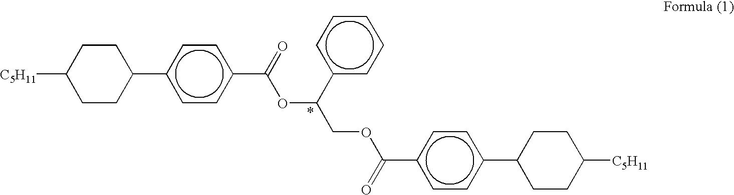
[0120] Chiral nematic liquid crystal compositions A1 and B1 were prepared. The composition A1 was prepared by adding 26 wt % of chiral material S-811 (manufactured by Merck & Co) to nematic liquid crystal A (dielectric constant anisotropy .DELTA..epsilon.: 17.3, refractive index anisotropy .DELTA.n: 0.29, nematic-isotropic phase transition temperature T.sub.NI: 113.degree. C.). The composition B1 was prepared by adding 30 wt % of chiral material S-811 to nematic liquid crystal B (.DELTA..epsilon.: 34.2, .DELTA.n: 0.20, T.sub.NI: 100.degree. C.) . These chiral nematic liquid crystal compositions A1 and B1 exhibited the cholesteric phase at a room temperature, and also exhibited selective reflection characteristics having peak reflective wavelengths around 640 nm and 490 nm, respectively. These chiral nematic liquid crystal compositions A1 and B1 had anisotropy values .DELTA.n of 0.22 and 0.16, respectively.

[0121] One of the substrates was formed of a PC (polycarbonate) film, on whic...


PUM


Abstract

A liquid crystal display apparatus includes a first liquid crystal layer having first liquid crystal exhibiting a cholesteric phase at a room temperature, and being tuned to selectively reflect light of a wavelength lambd1 within a visible wavelength range; and a second liquid crystal layer disposed on the first liquid crystal layer, having second liquid crystal exhibiting a cholesteric phase at the room temperature, and being tuned to selectively reflect light of a wavelength lambd2 within the visible wavelength range, wherein a difference between the selective reflection wavelengths lambd1 and lambd2 is in a range from 100 nm to 150 nm.

Description

[0001] This application is based on Japanese patent application No. 2001-93907 filed in Japan on Mar. 28, 2001, the entire content of which is hereby incorporated by reference.[0002] 1. Field of the Invention[0003] The present invention relates to a liquid crystal display apparatus, and particularly to a liquid crystal display apparatus of a reflection type including liquid crystals, which can selectively reflect light of specific wavelengths in visible light at a room temperature.[0004] 2. Description of Related Art[0005] A liquid crystal display apparatus basically has a pair of substrates and a liquid crystal layer held between the substrates. By applying a drive voltage to the liquid crystal layer, orientation of liquid crystal molecules is controlled to modulate external light incident to the liquid crystal layer so that images or the like can be displayed in an intended manner.[0006] Various manners have been proposed for display by the liquid crystal.[0007] In recent years, r...

Claims


Application Information

Patent Timeline
IPC IPC(8): G02B5/20G02B5/28G02F1/133G02F1/1333G02F1/1335G02F1/1337G02F1/1347G02F1/137
CPCG02F1/13718G02F1/13471
Inventor HISAMITSU, AKIHITOUEDA, NOBORUKOBAYASHI, NOBUYUKIUEDA, HIDEAKI
Owner MINOLTA CO LTD
Why Eureka
Try Eureka