Method for engine misfire detection in multi-cylinder internal combustion engines with multi-cylinder spark ignition

a multi-cylinder, spark ignition technology, applied in the direction of machines/engines, electric control, instruments, etc., can solve the problems of deterioration of exhaust gas values, inability to detect, and drop in torque caused by deterioration, so as to prevent the injection of the affected cylinder and reliable detection

Inactive Publication Date: 2002-10-31
ROBERT BOSCH GMBH
View PDF0 Cites 10 Cited by
  • Summary
  • Abstract
  • Description
  • Claims
  • Application Information

AI Technical Summary

Benefits of technology

[0003] Such methods utilize the realization that a combustion which does not take place within a cylinder of an engine causes characteristic changes of the trace of the torque of the engine compared to normal operation. From the comparison of the torque traces, one can distinguish between normal operation of the engine without misfire and so-called misfire-burdened operation. A misfire-burdened operation of one or several cylinders contributes to the total torque trace of the engine with a reduced contribution. This contribution can be determined by detecting the actual torques of the cylinders via an evaluation of the time-dependent trace of the crankshaft rotation or the camshaft rotation. According to the species method, a crankshaft angular region is assigned to a specific region of the piston movement of each cylinder or several simultaneously ignited cylinders. The crankshaft angle region is characterized as a segment. The segments, which belong to each cylinder or to the cylinders, are, for example, realized by markings on a transducer wheel coupled to the crankshaft. The segment time is the time in which the crankshaft passes over the corresponding angular region of the segment and is essentially dependent upon the energy converted in the combustion stroke. As a consequence of defective torque contributions, misfires lead to an increase of the ignition-synchronously detected segment times which are determined for each segment by scanning the markings on the transducer wheel by a suitable sensor. The more even the engine runs, the less will be the differences between the individual segment times. As already known from the state of the art, for example, from DE-OS 4,138,765, an index for the rough running of the engine is computed from the differences of the segment times. Additional boundary conditions are mathematically compensated and are, for example, the increase of the engine rpm for a vehicle acceleration. The rough running value is computed for each ignition of a cylinder or of simultaneously igniting cylinders. In a subsequent method step, the rough running value is compared ignition-synchronously in a desired value comparator to a threshold value. If the determined rough running value exceeds the threshold value, then this is evaluated as a misfire of the affected cylinder. The threshold value is, if needed, dependent upon operating parameters such as load and rpm. If misfires are determined, then their number is added. When a specific misfire rate is exceeded then, for example, a suitable warning device indicates this unevenness.
[0008] It has been shown to be practical in this context, for the additional check of misfire-burdened cylinders, to apply the engine intervention in a further method step to the cylinder which is not misfire burdened and which was at first not switched off. Simultaneously, the cylinder is switched in which has been predetermined as being burdened by misfires. After carrying out this method step, the change of the rough running value in the crankshaft segment region is determined by a further measurement. A corresponding increase of the rough running values serves as final indication that the cylinder, which is already recognized as misfire-burdened, is actually affected because, in this case, both cylinders do not supply a torque contribution because of the corresponding switchover.
[0009] The further measurement of the change of the rough running values, which was carried out in the context of the check, can also take place via a desired value comparison to the threshold value for the misfire detection in individual cylinder ignition.

Problems solved by technology

The deterioration of the exhaust gas values is caused by misfires as a consequence of an engine defect.
In internal combustion engines having several simultaneously igniting cylinders, the problematic results that for a misfire detection for a crankshaft segment wherein, for example, two cylinders ignite simultaneously, no detection can take place as to which of the two cylinders has combustion misfires.
Furthermore, for internal combustion engines having several simultaneously igniting cylinders, the problem is present that, for misfire-burdened operation of one of these cylinders, the drop in torque caused thereby is present and is measured at the crankshaft but, in contrast to the misfire of a single igniting cylinder, the torque reduction is considerably less because the other cylinder exhibits a normal combustion operation.
This has the consequence that, when comparing the rough running values of crankshaft segment regions having several simultaneously igniting cylinders, misfires, under certain circumstances, cannot be detected because of the threshold value which is necessarily set higher for a detection with an individual ignition.

Method used


Image

  • Method for engine misfire detection in multi-cylinder internal combustion engines with multi-cylinder spark ignition
  • Method for engine misfire detection in multi-cylinder internal combustion engines with multi-cylinder spark ignition

Examples


Embodiment Construction

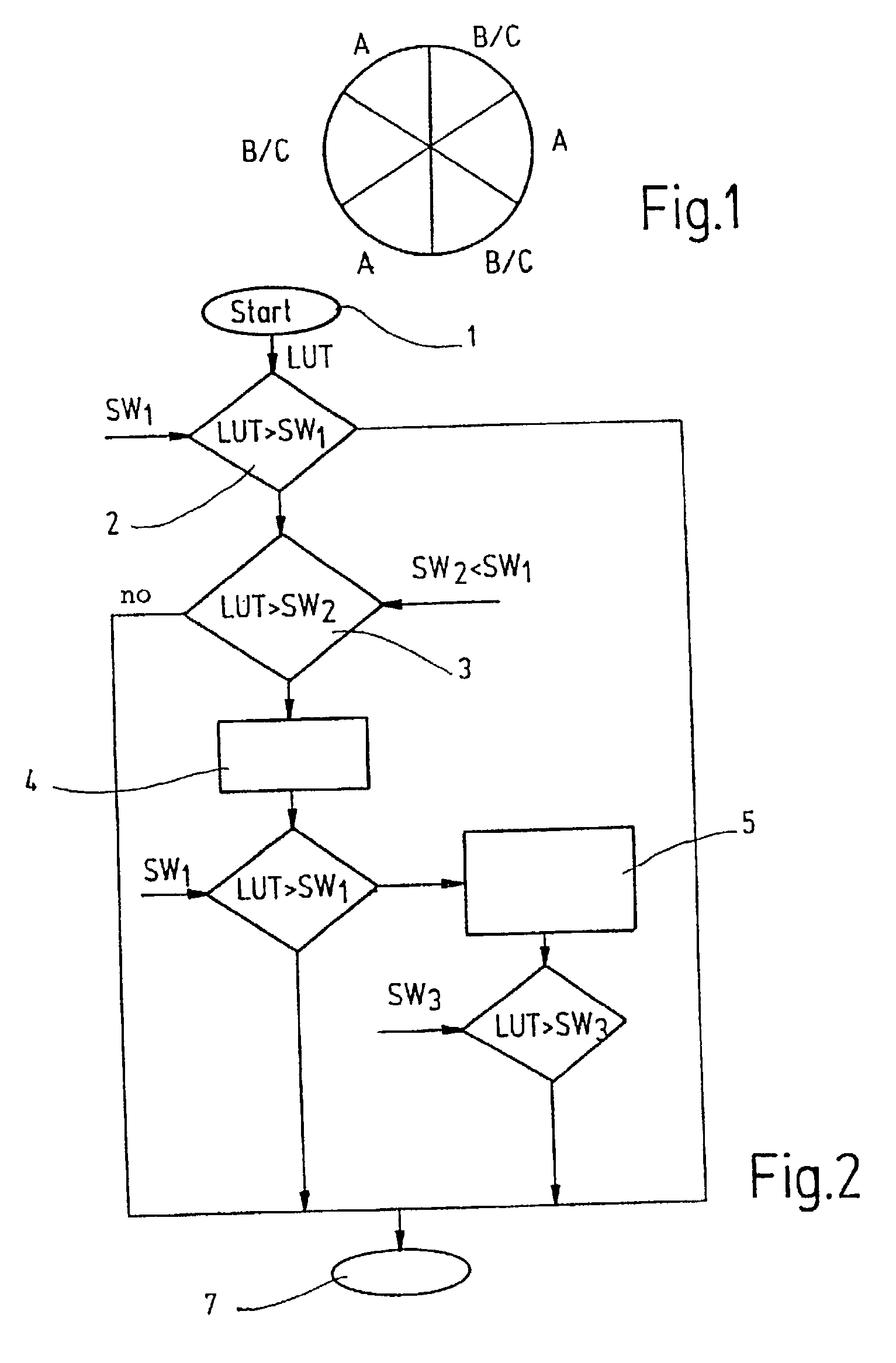
[0014] The method of the invention can, for example, be applied to an 18-cylinder engine. The engine is comprised of three cylinder banks A, B and C. A crankshaft revolution of 360 degrees is shown in FIG. 1 subdivided into six crankshaft segments. A total of six ignitions takes place in different cylinders of the engine during a crankshaft revolution. The cylinders of the cylinder bank A ignite individually; whereas, respective cylinders of cylinder banks B and C have a common ignition time point. The ignition sequence for a crankshaft revolution shown in FIG. 1 can be defined exemplary as follows:

[0015] 1st ignition operation: cylinder 1 of bank A;

[0016] 2nd ignition operation: cylinder 1 of bank B simultaneously with cylinder 1 of bank C;

[0017] 3rd ignition operation: cylinder 2 of bank A;

[0018] 4th ignition operation: cylinder 2 of bank B simultaneously with cylinder 2 of bank C;

[0019] 5th ignition operation: cylinder 3 of bank A; and,

[0020] 6th ignition operation: cylinder 3 of...


PUM


Abstract

The invention relates to a method for detecting combustion misfires in multi-cylinder internal combustion engines having several simultaneously igniting cylinders wherein, for each crankshaft rotation, rough running values are determined by measuring segment times, the segment times including the times, which correspond to the piston movement of individual cylinders after their ignition time point, wherein the crankshaft passes through an associated circular segment angular region. A combustion misfire is determined in the affected crankshaft circular segment regions from the determined rough running values LUT for crankshaft segment regions having several simultaneously igniting cylinders via a desired value comparison to a threshold value SW2, which is lower in value than the threshold value SW1 for the misfire check in crankshaft segment regions having individually igniting cylinders. For a combustion misfire in a crankshaft segment region having simultaneously igniting cylinders causing a misfire operation in one of these cylinders, a misfire operation is caused by a suitable engine intervention and by measuring the change of the rough running values in the crankshaft segment region having the simultaneously igniting cylinders, the cylinder is determined by the engine intervention which exhibits a combustion misfire without engine intervention.

Description

[0001] The invention relates to a method for detecting combustion misfires in multi-cylinder internal combustion engines having several simultaneously igniting cylinders with the features set forth in the preamble of claim 1.STATE OF THE ART[0002] Methods for detecting combustion misfires are utilized in spark-ignition engines in order to, on the one hand, detect an uneven engine running and to minimize the uneven running by suitable control arrangements while, on the other hand, and above all, to avoid a deterioration of exhaust-gas values and to protect the exhaust-gas catalytic converter. The rough running of the engine can, for example, be caused by valve coking or, in direct injecting engines, by quality scattering of the characteristic values of the injection valves. The deterioration of the exhaust gas values is caused by misfires as a consequence of an engine defect. If an engine defect is detected, which is apparent because of a misfire, then the driver can, for example, be...

Claims


Application Information

Patent Timeline
IPC IPC(8): G01M15/04F02D41/00F02D41/14F02D41/22F02D41/34F02D45/00G01M15/11
CPCF02D41/0085F02D41/1498G01M15/11F02D2200/1015F02D41/22F02P17/02
Inventor LEHNER, MICHAELOERTEL, HEIKORIES-MUELLER, KLAUS
Owner ROBERT BOSCH GMBH
Why Eureka
Try Eureka