
Method and apparatus for producing laminates

a technology of apparatus and laminates, applied in the direction of layered products, layered products, chemical apparatus and processes, etc., can solve the problems of significant productivity drop, component volatilization, appearance but also quality damage,

Inactive Publication Date: 2002-10-24
FUJIFILM HLDG CORP +1
View PDF8 Cites 7 Cited by
  • Summary
  • Abstract
  • Description
  • Claims
  • Application Information

AI Technical Summary

Benefits of technology

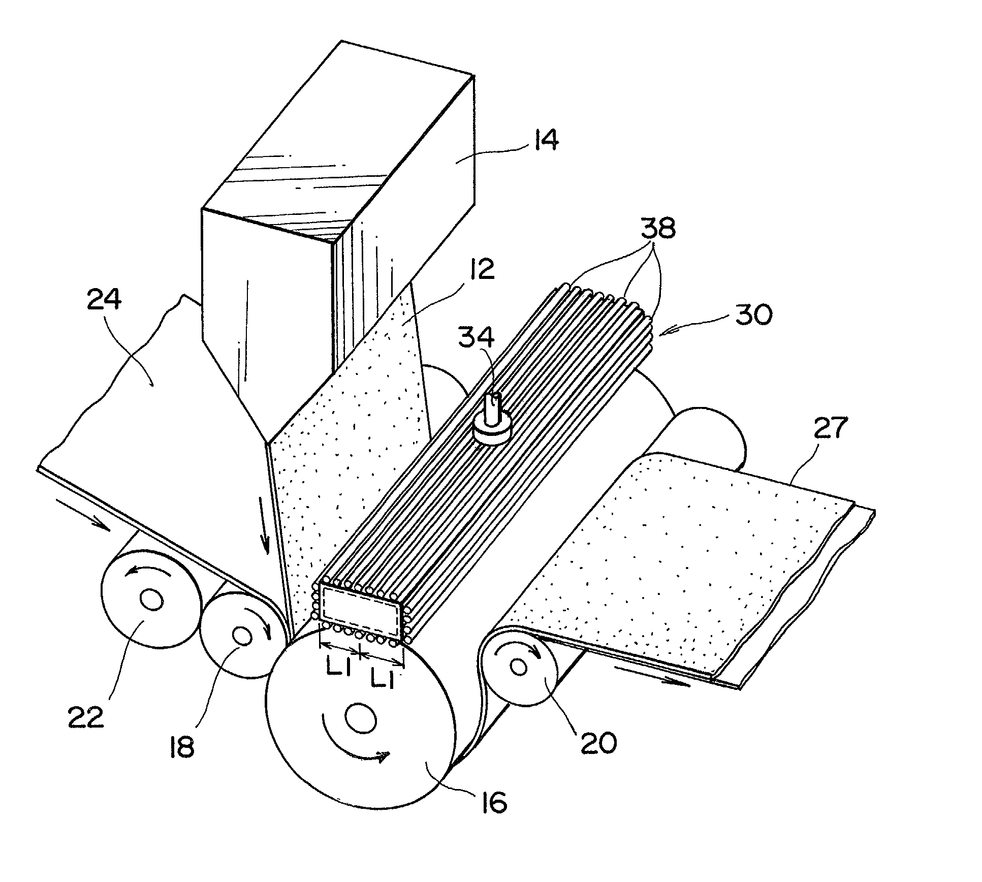
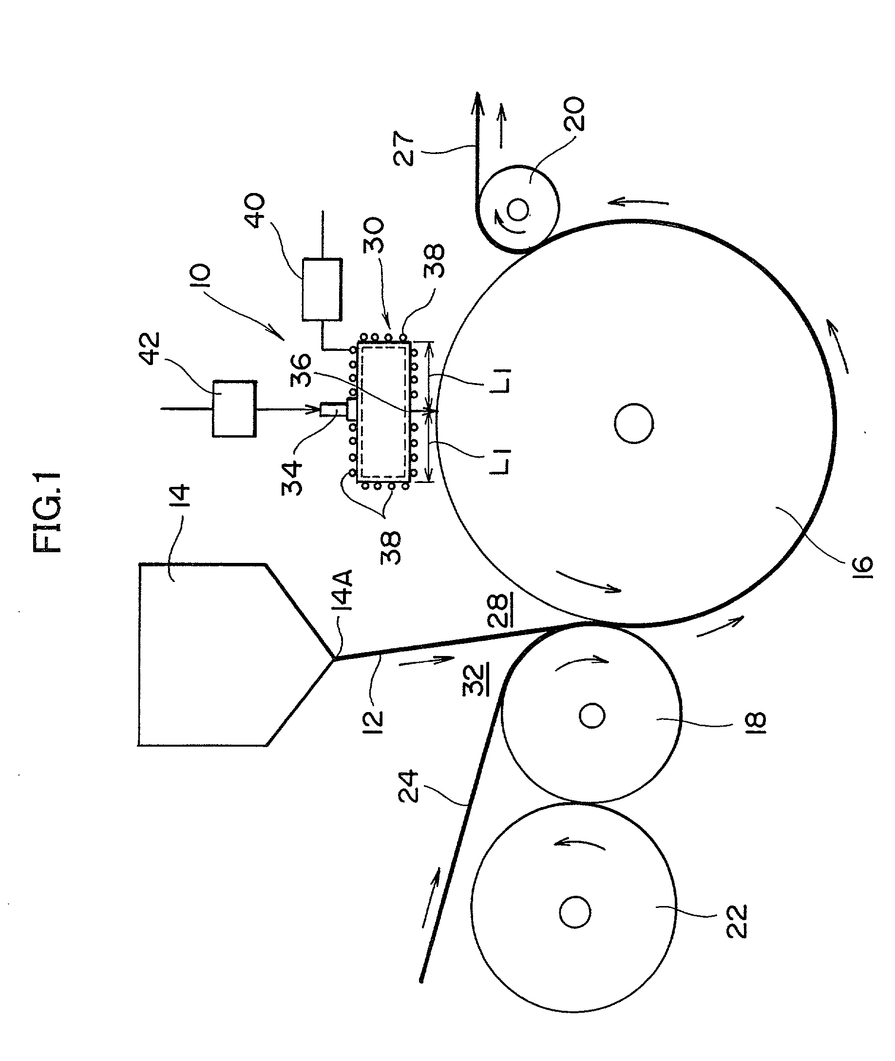
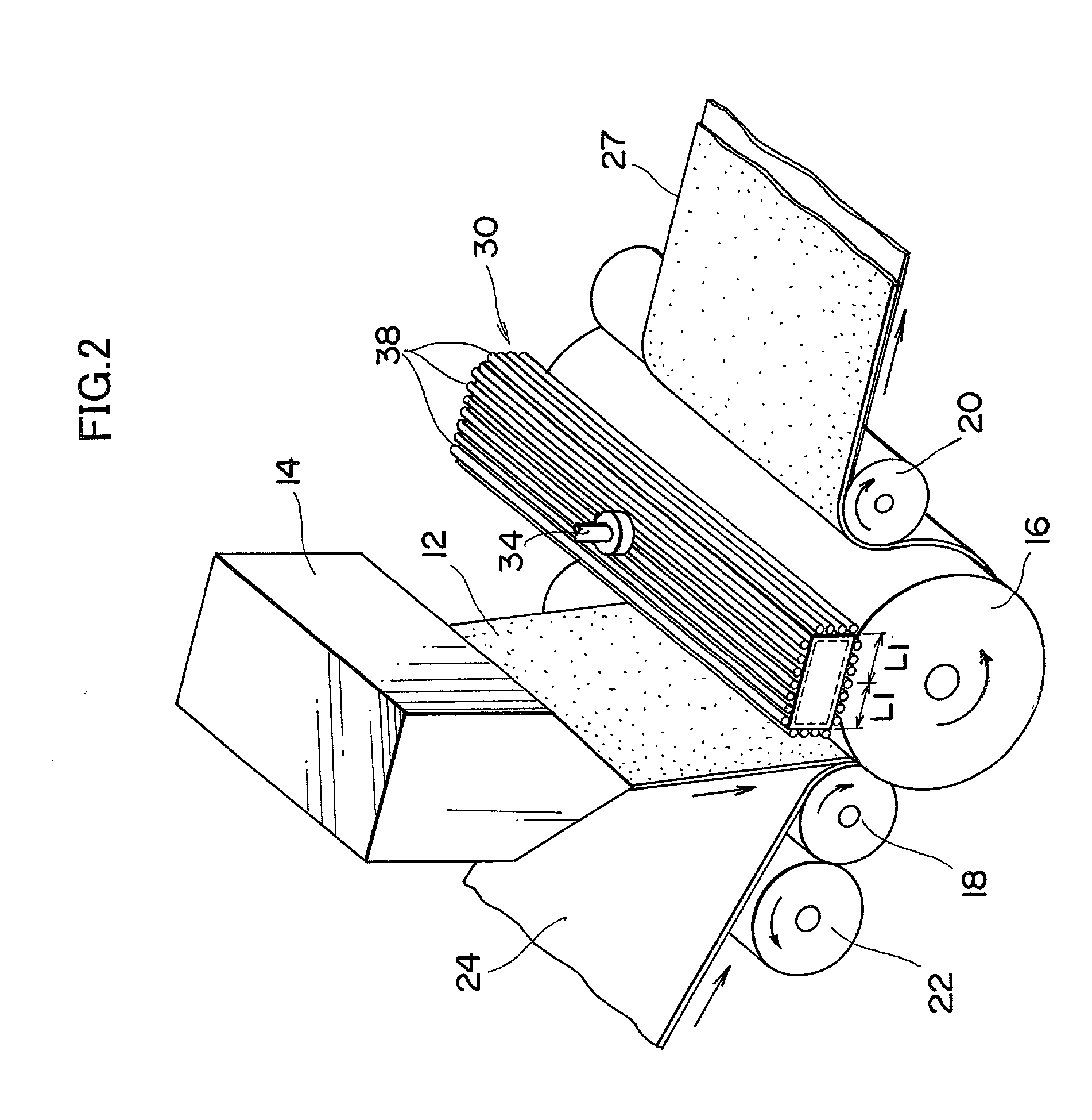
[0012] Preferably, the gas blown from the blower is heated at a temperature not below a temperature (.degree. C.) determined by subtracting 150 (.degree. C.) from the temperature (.degree. C.) at which the blower is heated. Thereby, a drop in temperature of the blower by the blowing of the gas is prevented, and the volatile component is prevented from sticking to the blower more reliably.
[0014] According to the present invention, the blower is heated at a temperature equal to or higher than the volatilization temperature of the volatile component volatilized from the thermoplastic resin extruded in molten conditions from the extruding die by the blower heater, so that the volatile component is immediately volatilized without sticking to the blower. Thereby, the volatile component is prevented from sticking to the blower.
[0015] Preferably, the laminate producing apparatus further comprises a gas heater which heats the gas to be blown through the blower at a temperature not below a temperature (.degree. C.) determined by subtracting 150 (.degree. C.) from the temperature (.degree. C.) at which the blower is heated. Thereby, a drop in temperature of the blower by the blowing of the gas is prevented, and the volatile component is prevented from sticking to the blower more reliably.
[0017] When a gas is blown from the nozzle, a negative pressure is provided in the surroundings of the nozzle to suck therein the air around the blower more easily, and thus the blower, rollers located near the blower and the product tend to be smeared with the volatile component. According to the present invention, the apparatus is configured to prevent this situation. Specifically, the nozzle is located at a distance of 15 mm or greater from the edge of the blowing face, thus preventing more reliably the surroundings of the blower from being influenced by the negative resulting from the blowing of the gas from the nozzle.

Problems solved by technology

However, there is a disadvantage that because high-temperature thermoplastic resin is extruded in molten conditions from the extruding die, a volatile component volatilized from the resin film of thermoplastic resin is stuck and accumulated on the blower, and a part of the components is dropped onto the cooling roller, the nip roller, the substrate, the product and the like to smear the roller, product and the like.
In particular, if the volatile component is dropped onto the product, not only the appearance but also quality of the product will be damaged.
If the product, roller and the like are smeared with such components, the production line should be stopped on a temporary basis to conduct cleaning, leading to a significant drop in productivity.
Therefore, there are no possibilities that the volatile component is stuck and accumulated on the blower 30.
The upper limit of the temperature of the blown gas is not particularly defined, but heating the blown gas more than necessary is not recommendable because energy is consumed in vain, and risks such as ignition may arise if the blown gas is heated at a temperature equal to or higher than the ignition point of the volatile component (420.degree. C. for the thermoplastic resin used in Examples described later).

Method used


Image

  • Method and apparatus for producing laminates
  • Method and apparatus for producing laminates
  • Method and apparatus for producing laminates

Examples


example 1

[0042] In Example 1, the same nozzle as that of Comparative Example 1 was placed at a distance of about 12.5 mm from the edge of the blowing face, and heaters as well as thermocouples were provided in a plurality of positions outside the blower, and the temperature was controlled so that the blower was kept at a temperature of 350.degree. C. In addition, a gas was blown from the blower at a flow rate of 50 m / second, and the blown gas was heated at 200.degree. C., which is lower than the temperature of the blower by 150.degree. C.

example 2

[0043] In Example 2, lamination was carried out in the same manner as Example 1 except that the diameter of the blower was increased so that the nozzle was placed at a distance of 15 mm from the edge of the blowing face.

example 3

[0044] In Example 3, lamination was carried out in the same manner as Example 1 except that the clearance of the nozzle of the blower was increased to 0.4 mm so that the flow rate of the blown gas was 30 m / second.


PUM

PropertyMeasurementUnit
Speedaaaaaaaaaa
Distanceaaaaaaaaaa
Temperatureaaaaaaaaaa

Abstract

Rollers, substrates, products and the like are not smeared with a sticky volatile component when a gas is blown from a blower provided near an extruding die to produce laminates. The blower is heated by a heater at a temperature not below the volatilization temperature of the volatile component volatilized from a resin film of thermoplastic resin extruded in molten conditions from the extruding die, and therefore the volatile component cannot stick on the blower and is immediately volatilized on the blower.

Description

[0001] 1. Field of the Invention[0002] The present invention relates to an apparatus for producing laminates, and in particular to an apparatus for producing laminates having a blower for blowing a gas near an extruding die.[0003] 2. Description of the Related Art[0004] For producing laminates such as substrates for photographic printing paper, an extrusion laminate method (also referred to as extrusion coating method) is widely employed in which a resin film of thermoplastic resin such as polyolefin extruded from an extruding die is applied to a running substrate or web and press-bonded thereto by nipping the film and the substrate together at a nip point located between a nip roller and a cooling roller, thereby laminating the substrate with the resin film.[0005] In the production of laminates, a various kinds of gases are blown from a blower provided near the extruding die for various purposes. For example, Japanese Patent Application Publication No. 63-246227 discloses that a ga...

Claims


Application Information

Patent Timeline
IPC IPC(8): B29C48/08B29C48/91B29K23/00B29L9/00B32B37/15
CPCB29C47/0021B32B2309/66B32B37/153B29C47/8845B29C48/08B29C48/91B29C48/914
Inventor KATSUMOTO, RYUICHIWAKI, YOSHIFUMIKEGASAWA, TADAHIRO
Owner FUJIFILM HLDG CORP
Learn More