
Satelite-based seismic mobile information and control system

Inactive Publication Date: 2002-10-17
VERITAS DGC
View PDF7 Cites 38 Cited by
  • Summary
  • Abstract
  • Description
  • Claims
  • Application Information

AI Technical Summary

Benefits of technology

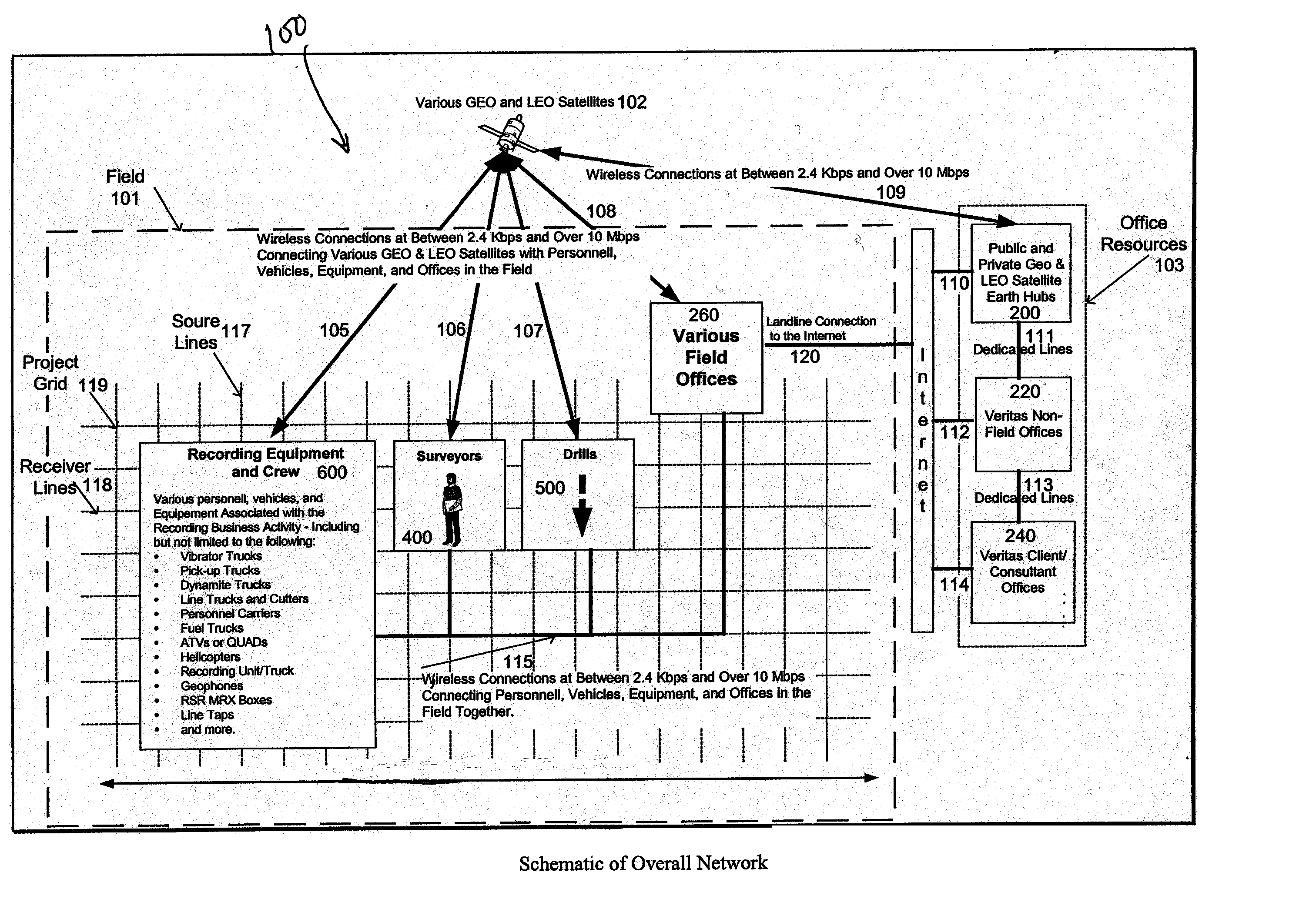
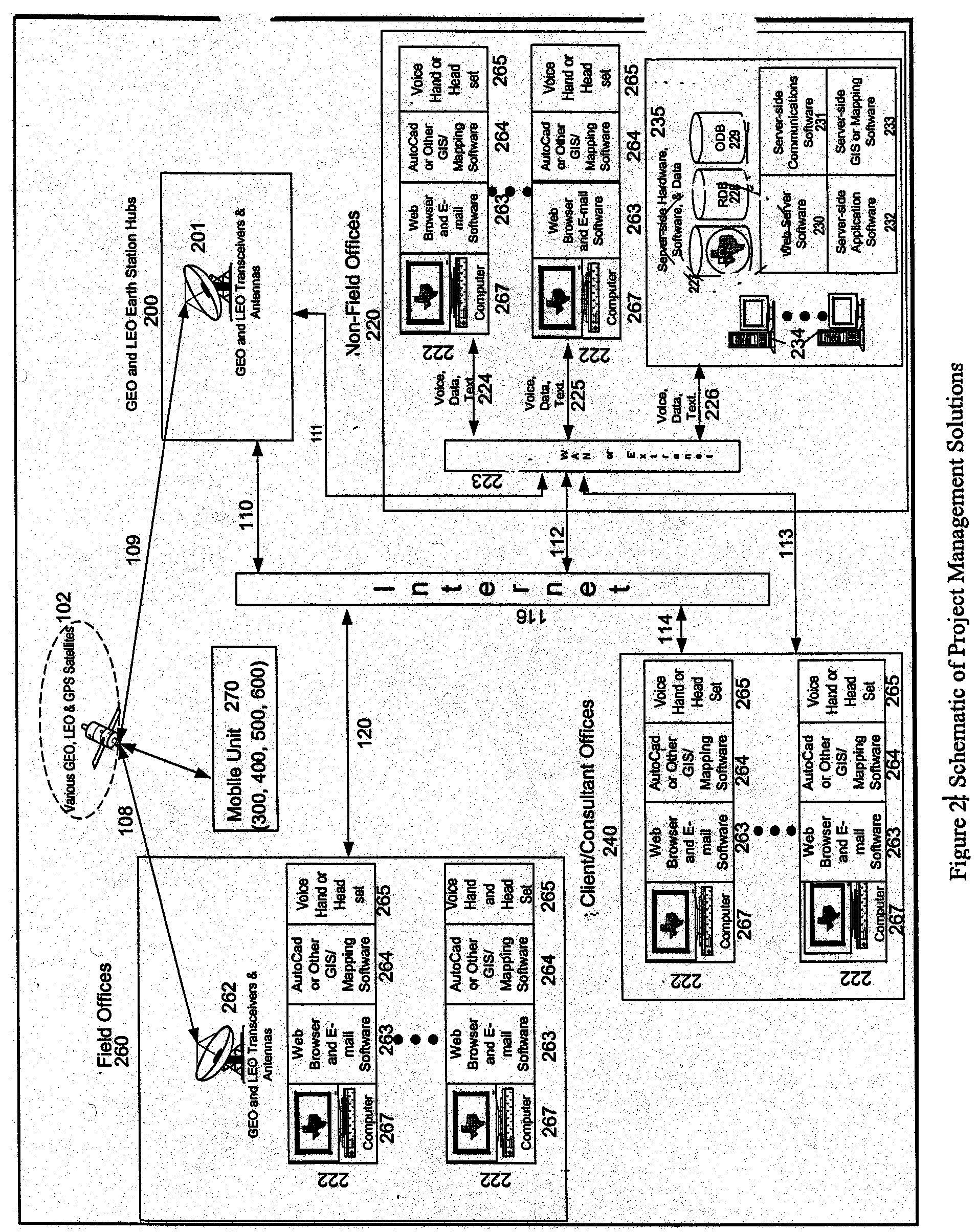
[0032] The deficiencies of the prior art described above are solved in large part by a real time data gathering, quality control (QC) and information distribution system, comprising field resources, satellite resources, and office resources that are located at a different site from the field. The field resources include various personnel, portable offices or trailors, equipment, and vehicles located in the general vicinity of the area to be surveyed. The field resources also include mobile and fixed transceivers allowing the field resources to communicate to the office resources via one or more satellites and experts at an information and control center (ICC) communicate back to field entities. The office resources include the ICC, client and consultant facilities, and one or more public and / or private satellite earth station hubs. The seismic system advantageously facilitates real or near real time transmission of assets, data, voice, and text between the field, the ICC, and client and consulting facilities, thereby providing an efficient seismic operation.

Problems solved by technology

Periodically, equipment malfunctions.
Managing the field resources, however, becomes increasingly problematic as the size of the project area increases.
Poor quality maps (i.e.., inaccurate maps or maps which have not been recently updated) detrimentally impact the quality of seismic survey.
Using the pre-plot coordinates and standard, albeit not highly accurate positioning techniques, the field personnel estimate the location in the field corresponding to the pre-plot coordinate.
Unfortunately, it is rarely possible to position the source and receiver equipment exactly at the pre-plot coordinates.
Ponds, roads, and other obstructions not shown on the maps used by the survey designers may prevent the equipment from being positioned where specified by the survey.
Additionally, even though GPS provides accurate positioning data, the actual location of the equipment still may not exactly match the pre-plot coordinates because of inaccuracies in the GPS system and / or lack of skill in the personnel using the GPS system.
At times, GPS equipment may malfunction and personnel may make blunders thereby resulting in erroneous coordinates for the source and recorder points.
Any discrepancy between the actual and pre-plot coordinates may impact the interpretation of the resulting seismic data.
The time lag occurs because communication of data from the field to the home office is not efficient.
The inefficiency results from the lack of an electronic communications infrastructure between the field and the office environment.
Considerable and undesirable time and expense is associated with reshooting a record or resurveying a point for which equipment must be brought back and set up again.
Bird dogs are usually highly trained and expensive resources that add to the cost of the seismic survey.
Without bird dogs, however, the client has little insight into the activity in the field as it occurs.
Further, poor quality and / or outdated maps contribute to errors in the design of the survey.
Field personnel, for example, may update a map, but there may be a considerable time lag before the updates are provided to the experts in the home office.
Further, the inability to accurately track equipment causes inefficiencies in the coordination of mobile units and people.
Inefficient tracking of mineral rights and land ownership information associated with permitting is another problem in the project management area driving up the cost of the survey.
If a different client wishes to survey the same area, that client, or its survey company, must undesirably repeat the same research into ownership and permit issues.
Project management in conventional seismic survey operations usually requires highly skilled, and thus expensive, labor in the field rather than in the office environment.
Further, scattering such skilled personnel across the globe at various seismic project sites does not permit the beneficial sharing of information between the various skilled professionals.
Mobilization and demobilization of equipment and personnel has its own set of problems.
For instance, conventional seismic operations do not have a highly accurate, efficient mechanism for tracking the location of the equipment including the vehicles to transport the equipment.
It thus is difficult to keep track of transportation vehicles, some of which may still be loading equipment from a previous job while other vehicles are deploying equipment to the next job site hundreds of miles away.
The inability to accurately and inefficiently track equipment makes inventory control problematic.
One piece of equipment may be stolen or misplaced and not noticed as missing for several days.
Additionally, conventional mobilization and demobilization systems do not provide a mechanism for accurately monitoring the time field personnel actually spend working, thereby potentially creating inaccuracies in client billing.
Shortcomings in the surveying phase include excessive waste of time and money having to re-stake points when the surveyor or geophysicist reviews the QC data and determines that a particular surveyed point or shot record must be rerun.
As noted above, the increased costs includes bringing equipment back to the site of the original shot record, setting up the equipment again, and repositioning the point or rerunning the shot record.
This process may cost 2 to 3 times the cost of the initial record.
In addition, typical seismic survey systems force field personnel to repetitively enter and log the same data leading to longer survey times at higher cost to the client.
Not only is this a time consuming and expensive process, considerable room for error exists because of the repeated human involvement with the data entry.
Surveying problems also include a lack of real-time integrity monitoring available to the client.
As such, the client generally is not able to monitor the integrity of the survey as it is occurring without incurring the substantial cost of hiring a bird dog in the field.
Additionally, surveying suffers from excessively long time periods in the communication loop between field personnel and the geophysicists in the home office.
In the drilling area, there is considerable redundancy involved with recording and logging drill information.
This process is slow and error prone.
These flags often are washed away by rain, buried by snow, or destroyed by cattle or field cultivation.
Extra time is expended, at increased cost to the client, to relocate the source point, or the hole may be missed altogether (i.e.., not drilled).
Geophysicists in the home office and the client generally are not provided with the recorded quality control data fast enough to analyze the data for accuracy while the equipment is still on location.
The inability of conventional seismic systems to provide QC data to the client quickly forces the client undesirably to hire expensive bird dogs in the field as noted previously.
Also, currently no conventional seismic system has the capability to transmit all the core seismic data back to the office environment for faster processing and delivery to the client as the end product.
Such activities typically are performed at various sites across the globe making coordination at times a monumentally difficult task.
The problems and inefficiencies of conventional seismic operations, some of which are outlined above, have plagued the seismic industry for a long time.

Method used


Image

  • Satelite-based seismic mobile information and control system
  • Satelite-based seismic mobile information and control system
  • Satelite-based seismic mobile information and control system

Examples


Embodiment Construction

Notation and Nomenclature

[0043] Certain terms are used throughout the following description and claims to refer to particular system components. As one skilled in the art will appreciate, components may be referred to by different names. This document does not intend to distinguish between components that differ in name but not function. In the following discussion and in the claims, the terms including and comprising are used in an open-ended fashion, and thus should be interpreted to mean including, but not limited to. Also, the term couple or couples is intended to mean either an indirect or direct electrical connection. Thus, if a first device couples to a second device, that connection may be through a direct electrical connection, or through an indirect electrical connection via other devices and connections.

[0044] The term survey is used in two senses; the first in the context of positioning, i.e., the determination of coordinates, while the second meaning is within a broader...


PUM


Abstract

<heading lvl="0">Abstract of Disclosure< / heading> A seismic system, Seismic Mobile Information & Control System (Seis-MICS) comprising field resources, satellite resources, and office resources. The field resources include various personnel, equipment, and vehicles located in the general vicinity of the seismic project. The field resources include transceivers permitting various of the field resources to communicate directly, or indirectly, to the office resources via one or more satellites. The office resources include satellite earth hubs / stations, a server-side hardware, software, and data store, and user workstations. The seismic system advantageously facilitates real or near real time transmission of data between the field and office environment, thereby providing an efficient seismic operation.

Description

Cross Reference to Related Applications[0001] This is a non-provisional application based on and claiming priority to U.S. Provisional Application Serial No. 60 / 131,906, filed April 30, 1999, incorporated herein by reference in its entirety.Background of InventionField of the Invention[0003] The present invention generally relates to seismic operations. More particularly, the invention relates to seismic operations using satellites to provide communication between the field of operations and the office environment. Still more particularly, the invention relates to an integrated satellite-based seismic information system, facilitating efficient management of resources and assets in the field.Background of the Invention[0004] The field of seismology focuses on the use of artificially generated elastic waves to locate subsurface structures which may contain mineral deposits such as hydrocarbons, ores, water, and geothermal reservoirs. Seismology also is used for archaeological purposes...

Claims


Application Information

Patent Timeline
IPC IPC(8): G01V1/00G01V1/22
CPCG01V1/22G01V1/003
Inventor ROY , JAMESPORTSMOUTH , JACKIE L.A.KRAKIWSKY , EDWARD J.KRAKIWSKY , SEAN E.
Owner VERITAS DGC
Learn More