Hologram recording medium, hologram recording method and hologram recording and reproducing apparatus

Inactive Publication Date: 2002-10-10
PIONEER CORP
View PDF3 Cites 16 Cited by
  • Summary
  • Abstract
  • Description
  • Claims
  • Application Information

AI Technical Summary

Benefits of technology

[0013] Therefore, an object of the present invention is to provide a hologram recording medium, a hologram recording method, a hologram recording and reproducing method and a hologram recording and reproducing apparatus capable of performing the recording at a higher density and are able to be made compact.
[0048] According to one aspect of the hologram recording and reproducing method of the present invention, a gate light beam having a second wavelength for enhancing a recording sensitivity of the recording medium is irradiated to the recording medium coaxially with respect to the recording reference light beam so as to pass through a portion of the recording medium for crossing the signal light beam and the recording reference light beam and demarcate a volume smaller than that of the portion for crossing the signal light beam and the recording reference light beam in the recording step.
[0058] a gate light section for making a gate light beam of a second wavelength for enhancing a recording sensitivity of the recording medium convergent and approximately perpendicularly incident to the main surface of the recording medium coaxially with respect to the recording reference light beam, and forming the refractive index grating of one portion of the optical interference pattern which passes through a portion of the recording medium for crossing the signal light beam and the recording reference light beam and demarcates a volume smaller than that of this crossing portion;
[0065] A reproducing method using a phase conjugate wave is considered as one of methods for making a hologram memory system compact. Phase conjugate reference light (hereinafter called reproducing reference light) at a recording time with respect to reference light (hereinafter called recording reference light) at the recording time is used to realize this reproducing method using the phase conjugate wave. Namely, the phase conjugate wave reproducing method at the recording time is the same as the conventional case. However, in this reproducing method, at a reproducing time, phase conjugate light of the signal light is generated in an incident direction of the signal light by using the phase conjugate reproducing reference light having a symmetrical property opposed to that of the reference light at the recording time so that a Fourier transformation lens can be also used as a reverse Fourier transformation lens. Further, even when the phase of a wave front of the phase conjugate light is disturbed by passing this phase conjugate light through the recording medium and the lens, there is a nature of the phase conjugate light in which the phase disturbance is compensated and returned to its original state when the phase conjugate light again reversely passes through the recording medium and the lens. Accordingly, the recording and reproducing apparatus can be constructed by using a simple lens without requiring a lens of high performance thanks to the nature of the phase conjugate light. Therefore, the recording reproducing method is very effective to make the recording and reproducing apparatus compact in size.

Problems solved by technology

The recording medium having a large erasing time constant is generally low in recording sensitivity, and is a cause of the limited recording speed as a system.
Accordingly, a problem exists in that it is disadvantageous to make the system compact.

Method used


Image

  • Hologram recording medium, hologram recording method and hologram recording and reproducing apparatus
  • Hologram recording medium, hologram recording method and hologram recording and reproducing apparatus
  • Hologram recording medium, hologram recording method and hologram recording and reproducing apparatus

Examples


Embodiment Construction

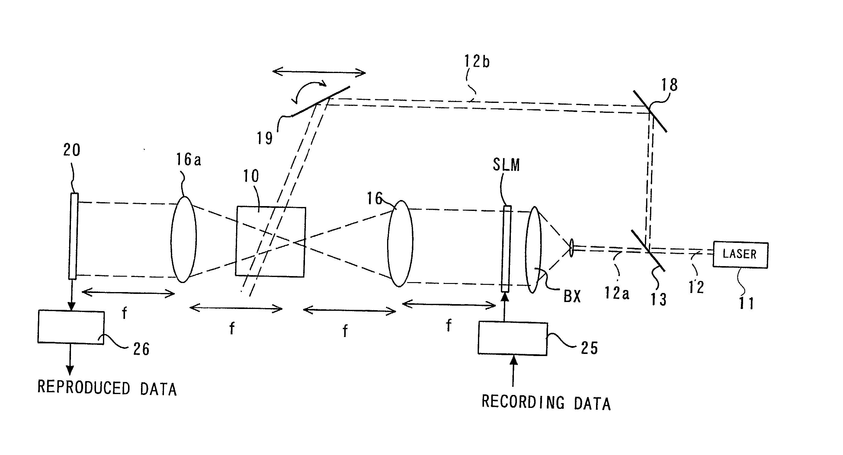
[0075] The embodiments of the present invention will next be explained with reference to the accompanying drawings.

[0076] A reproducing method using a phase conjugate wave is considered as one of methods for making a hologram memory system compact. Phase conjugate reference light (hereinafter called reproducing reference light) in a recording time with respect to reference light (hereinafter called recording reference light) in the reproduction time is used to realize this reproducing method using the phase conjugate wave. Namely, the phase conjugate wave reproducing method in the reproduction time is the same as the conventional case. However, in this reproducing method, at a reproduction time, the phase conjugate light of signal light is generated in an incident direction of the signal light by using the phase conjugate reproducing reference light having a symmetrical property opposed to that of the reference light in the reproduction time so that a Fourier transformation lens can...


PUM


Abstract

A hologram recording medium, a hologram recording method and a recording and reproducing apparatus are capable of recording an interference pattern onto a volume holographic memory at high density. In a hologram recording method for forming a plurality of areas of a refractive index grating corresponding to one portion of a three-dimensional light interference pattern of a coherent signal light beam and coherent reference light of a first wavelength modulated in accordance with information data within a recording medium made of a photo refractive crystal of a uniaxial crystal having a shape of parallel flat plates, the signal light beam and the recording reference light beam cross each other within the recording medium, and a gate light beam having a second wavelength for revealing recording sensitivity of the recording medium is simultaneously irradiated to the recording medium so as to pass through a portion of the recording medium for crossing the signal light beam and the recording reference light beam and demarcate a volume smaller than that of this crossing portion. In a reproducing step a reproducing reference light beam is generated by reflecting the recording reference light beam in the vicinity of the beam waist of the recording reference light beam.

Description

[0001] 1. Field of the Invention[0002] The present invention relates to a recording medium made of a photo refractive material, i.e., a so-called holographic memory, and particularly relates to a hologram recording method and an optical information recording and reproducing apparatus utilizing the holographic memory.[0003] 2. Description of Related Art[0004] A volume holographic recording system is known as a digital information recording system utilizing the principle of a hologram. This system is characterized in that an information signal is recorded onto a recording medium as a change in refractive index. A photo refractive material such as a lithium niobate monocrystal is used in the recording medium.[0005] Explanation will be made for a recording and reproducing method using a Fourier transformation as an example of conventional hologram recording and reproducing methods.[0006] As shown in FIG. 1, in a conventional 4f-system hologram recording and reproducing apparatus, a lase...

Claims


Application Information

Patent Timeline
IPC IPC(8): G03H1/02G03H1/04G03H1/30G11B7/00G11B7/0065G11C13/04
CPCG03H1/02G03H1/0248G03H2001/0268G03H2001/0413G03H2001/183G03H2222/34G03H1/26G03H2223/14G03H2260/54G11B7/0065G11B2007/0009G11C13/042G03H2222/56
Inventor TANAKA, SATORUMATSUSHITA, HAJIMEITOH, YOSHIHISAKOUNO, TOMOMITSUHATANO, HIDEKI
Owner PIONEER CORP
Why Eureka
Try Eureka