Iterative decoding of differentially modulated symbols

a differential modulation and decoding technology, applied in the field of digital communication, can solve the problems of code effectively being useless, c.sub.1 and c.sub.i+1 are in error, and degradation is much wors

Inactive Publication Date: 2002-09-26
TELEFON AB LM ERICSSON (PUBL)
View PDF4 Cites 6 Cited by
  • Summary
  • Abstract
  • Description
  • Claims
  • Application Information

AI Technical Summary

Problems solved by technology

Therefore, if s.sub.i is in error, this will typically result in that both c.sub.1 and C.sub.i+1 are in error.
In the case of binary block coding, where k information bits are encoded into n coded bits, the degradation is much worse.
This code would effectively be useless since a codeword will either be received without any errors, so that no error correction is needed; or the codeword will contain at least two errors, which cannot be corrected by the code in any event.
Also, in the case when a more powerful random error correcting code is employed, the performance will be heavily degraded because of the bursty nature of the errors.
The reason for using an interleaver / deinterleaver is that the communication channel over which the data is transmitted is typically changing in such a way that many consecutive received symbols can be unreliable, thus preventing an error correction code from working properly.
Although the above described procedure, which is well known in the art, does improve the performance for a coded system, the procedure is far from optimal in the case of differential encoding.

Method used


Image

  • Iterative decoding of differentially modulated symbols
  • Iterative decoding of differentially modulated symbols
  • Iterative decoding of differentially modulated symbols

Examples


Embodiment Construction

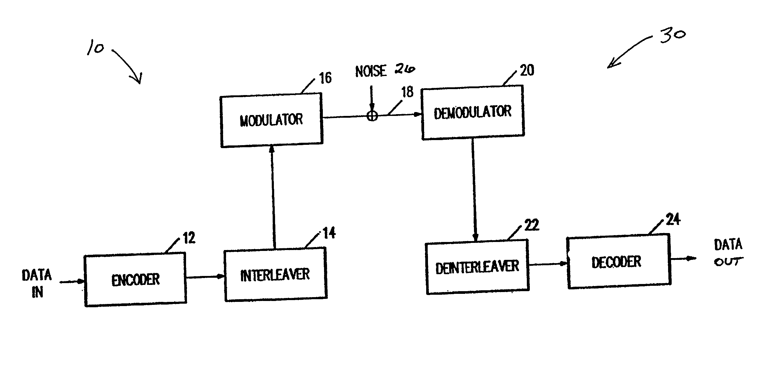
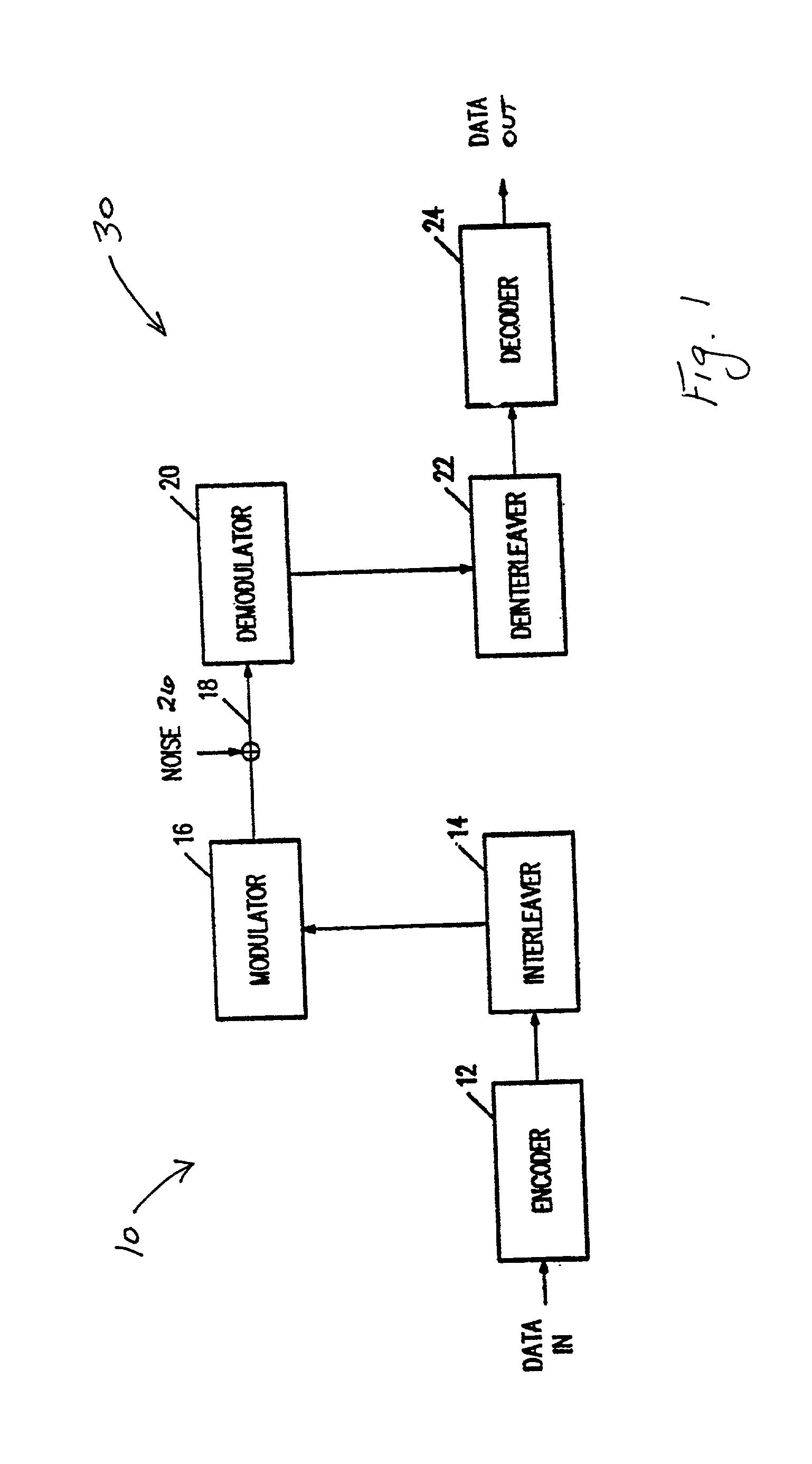
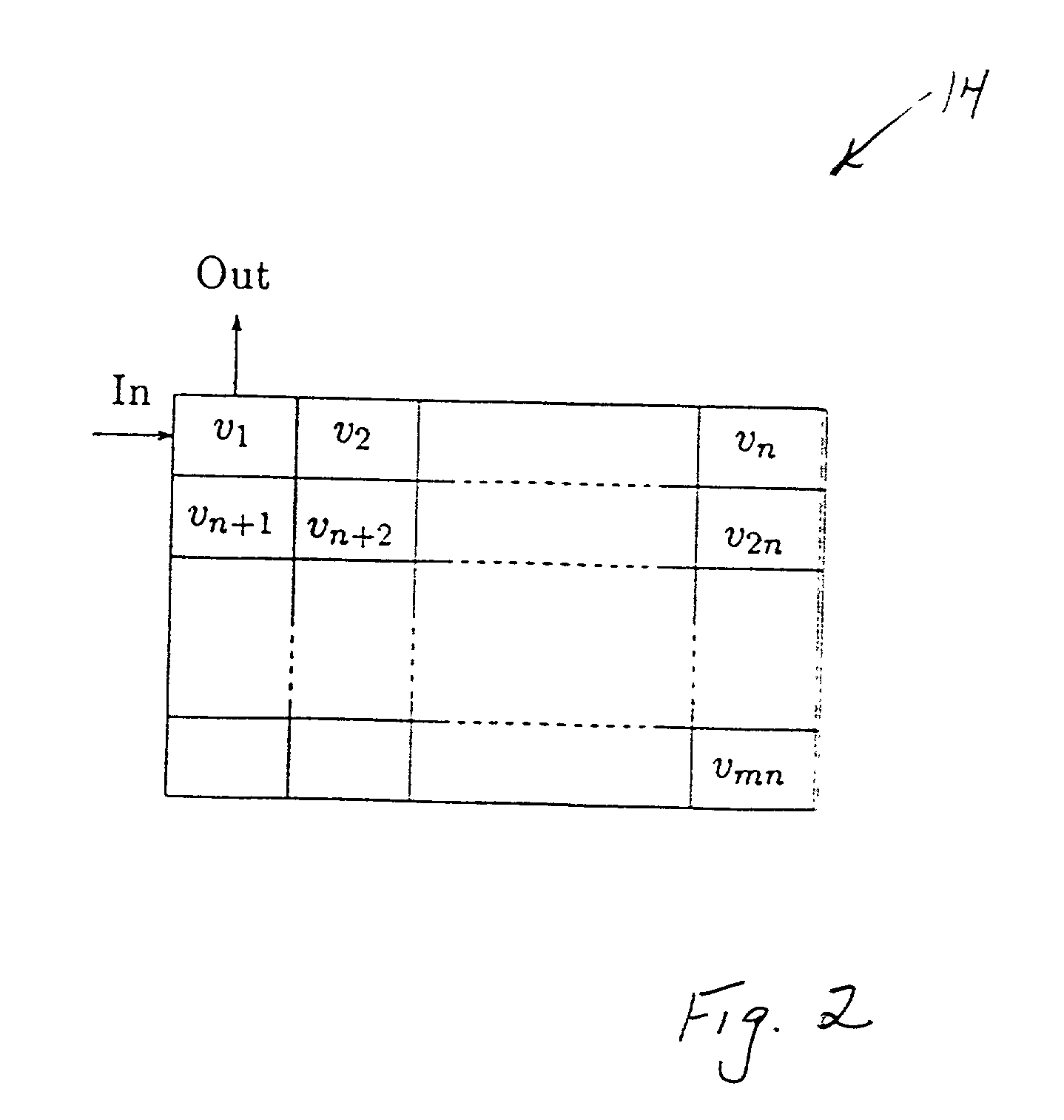
[0038] FIGS. 3-5 schematically illustrate the structure of a deinterleaver, such as the deinterleaver 22 of FIG. 1, to assist in explaining the present invention. As mentioned previously, the present invention relates to the decoding of block-coded data that has been transmitted by means of differential modulation such as DPSK; and it is assumed in the following discussion that the modulation is binary, although generalization to a larger alphabet will be made hereinafter.

[0039] Initially, in accordance with the present invention, an attempt is made to decode the m codewords in the deinterleaver in the usual manner, i.e., by using a random error correcting code. If this attempt is successful, the decoding process is completed. Now, assume that the number of rows in the deinterleaver is five (m=5); and, further, assume that all the errors are located as depicted in FIG. 3. (In FIGS. 3-5, the locations of the erroneous code symbols or bits in the deinterleaver are indicated by "X", wh...


PUM


Abstract

Method and apparatus for decoding block-coded data which has been transmitted by means of differential modulation. The method first attempts to decode all codewords using an error correcting code, and if at least one codeword is still not decoded, uses a correctly decoded codeword to locate a possibly erroneous code symbol in the at least one codeword, alters the possibly erroneous code symbol, and again attempts to decode the at least one codeword. The invention recognizes that errors in such data typically occur in pairs, and utilizes this property to improve the decoding process.

Description

[0001] 1. Field of the Invention[0002] The present invention relates generally to the field of digital communications; and, more particularly, to a method and apparatus for decoding block-coded data which has been transmitted by means of differential modulation.[0003] 2. Description of the Prior Art[0004] Differential modulation, such as differential phase shift keying (DPSK), is used in digital communications systems to avoid the need for an absolute phase reference. Because differential modulation is probably most commonly used in connection with PSK, the following description is made assuming that DPSK is the modulation. As will become apparent, however, differential modulation is also applicable to modulation formats other than PSK; and it should be clearly understood, that it is not intended to limit the invention to DPSK[0005] To further facilitate the following description, it is additionally assumed that the modulation is binary although it is also not intended to limit the ...

Claims


Application Information

Patent Timeline
IPC IPC(8): H03M13/05H03M13/27H03M13/37
CPCH03M13/05H03M13/2707H03M13/37
Inventor WILHELMSSON, LEIF
Owner TELEFON AB LM ERICSSON (PUBL)
Why Eureka
Try Eureka