
Test for brake fluid age and condition

a technology for automotive brake fluid and age, which is applied in the direction of color/spectral property measurement, instrumentation, chemical analysis, etc., can solve the problems of brake fluid vaporization under hot operating conditions, complete brake failure, and reduce the effectiveness of the braking system, so as to achieve the effect of easy and economical implementation

Inactive Publication Date: 2002-09-19
PHOENIX SYST
View PDF0 Cites 15 Cited by
  • Summary
  • Abstract
  • Description
  • Claims
  • Application Information

AI Technical Summary

Benefits of technology

[0013] Yet another goal is a procedure that can be carried out rapidly during regular automotive maintenance.
[0014] A final objective is a procedure that can be implemented easily and economically according to the above stated criteria.

Problems solved by technology

A low boiling point can cause the brake fluid to vaporize under hot operating conditions, such as during continuous braking on a downhill road.
Such vaporization can create pockets of compressible vapor in the system that dangerously reduce the effectiveness of the braking system.
This is the occurrence normally referred to as "brake fade" which, in extreme cases, can cause complete brake failure.
All types of glycol-based brake fluid are hygroscopic.
As a result of this property, they readily absorb moisture that reduces their boiling point and, if unchecked, can become dangerous.
If the color change indicates a higher-than-desirable copper concentration, the brake fluid is considered inadequate for safe operation and replaced without further tests.
Another important aspect of brake systems maintenance is the corrosive nature of some of their constituents, which, upon contamination of the brake fluid, progressively contribute to damage metallic tubing and other parts of the brake system.
If the color change indicates a higher-than-acceptable copper concentration, the brake fluid is considered degraded and contaminated, and therefore also corrosive and in need of replacement for proper maintenance of the vehicle's braking system.

Method used


Image

  • Test for brake fluid age and condition
  • Test for brake fluid age and condition
  • Test for brake fluid age and condition

Examples


Embodiment Construction

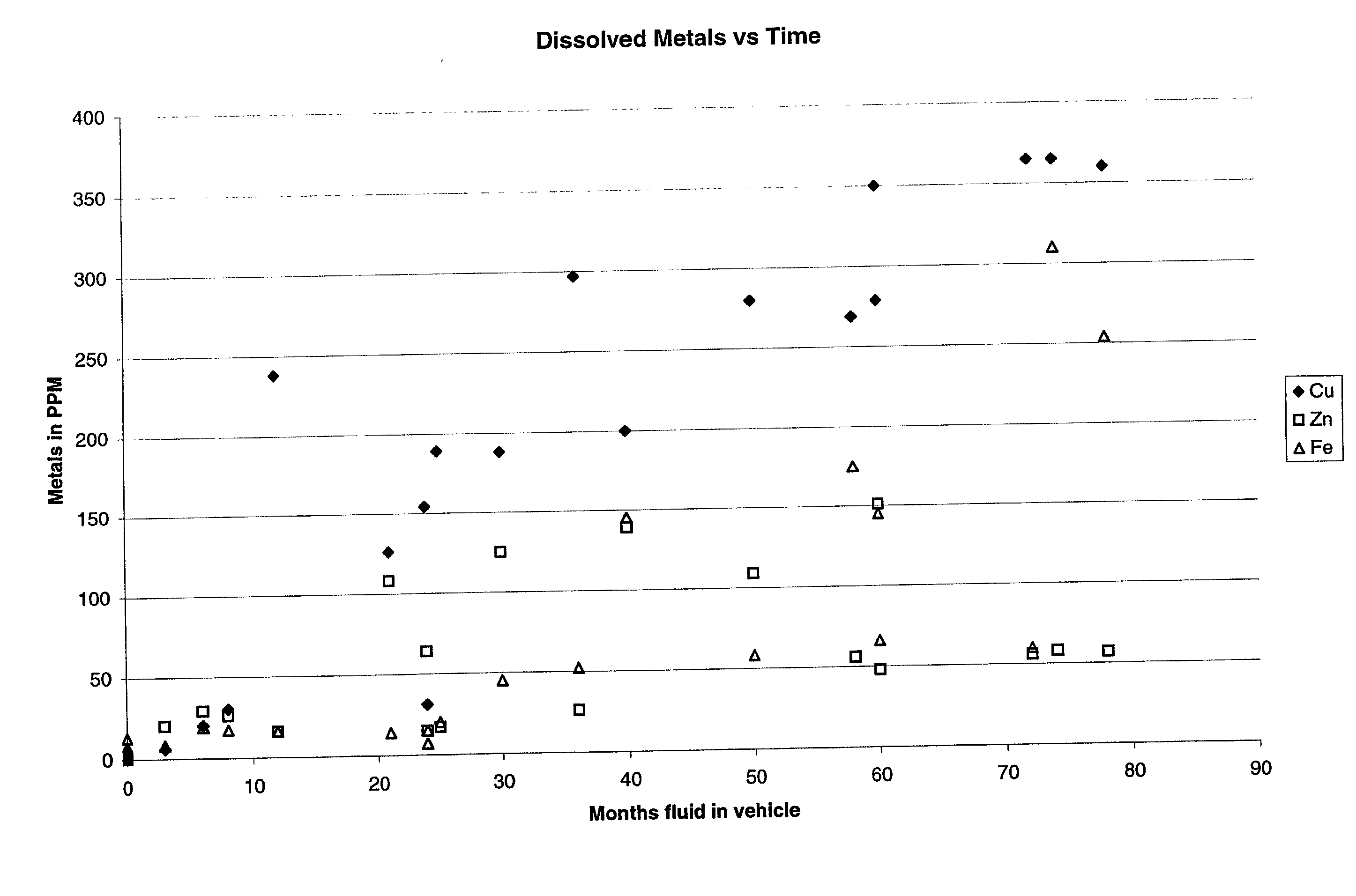
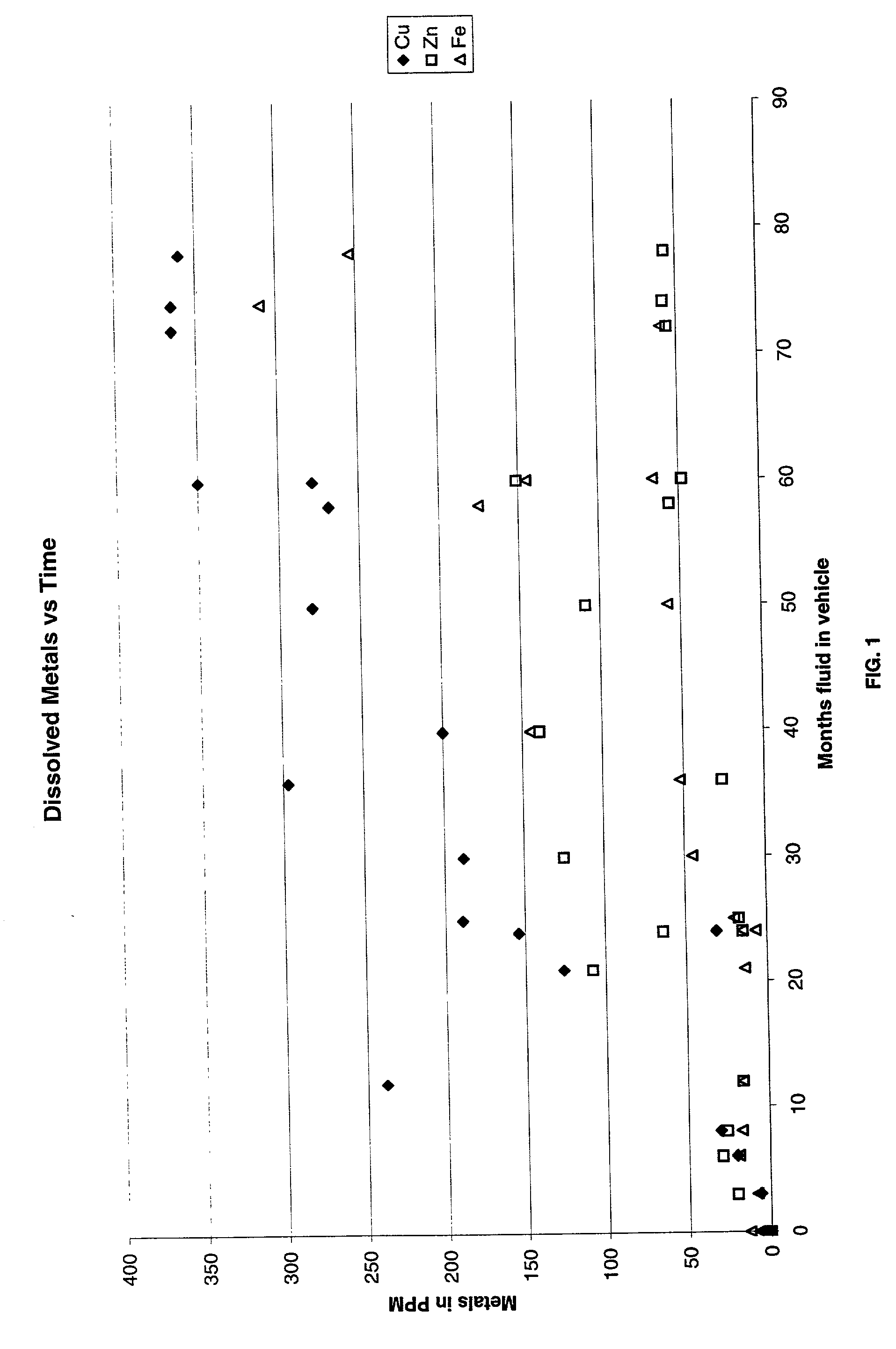
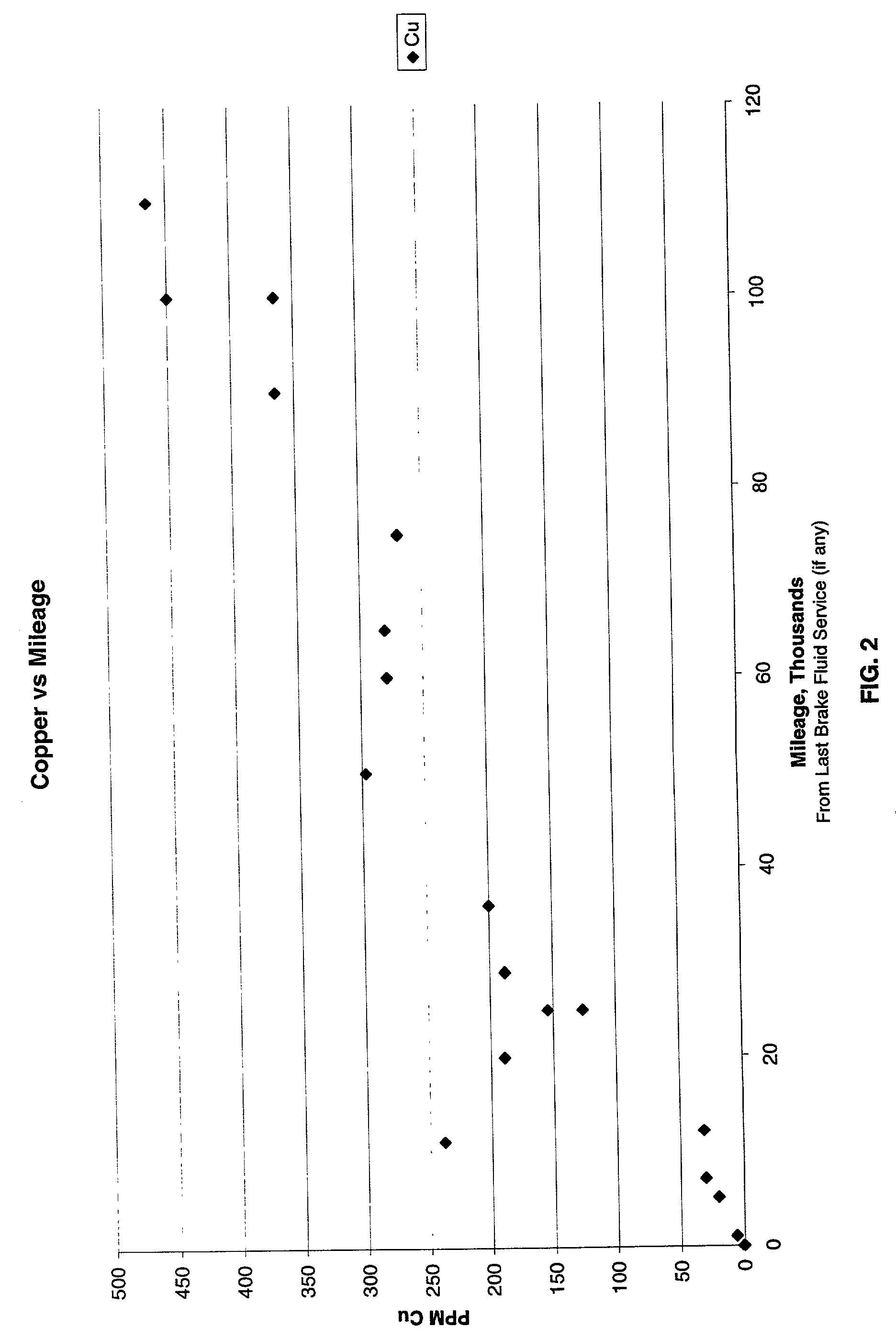
[0026] This invention is based on the realization that the brake-fluid concentration of copper, the principal metal previously disclosed as being predictably correlated to the degradation of the fluid's boiling point and reserve alkalinity, is also indicative of the fluid's service age and / or mileage; that is, the vehicle's virtual age. Accordingly, this correlation between service age and / or mileage and copper concentration is advantageously used to estimate the condition of the fluid and establish maintenance schedules based thereon.

[0027] Most brake lines consist of steel lined with a copper alloy and represent the largest surface area of metal in contact with brake fluid. A typical light-duty vehicle uses about 14 meters of such tubing with an inside diameter of about 2.5 mm, for a total internal surface area of about 1,200 cm.sup.2. Therefore, corrosion of these lines contributes relatively large amounts of copper ions to the fluid. The master and slave cylinders include steel ...


PUM


Abstract

A correlation is derived between a variable, defined as "virtual age," indicative of brake fluid's service age and / or mileage and the concentration of copper in the fluid. Virtual age is utilized to estimate the degree of degradation of the fluid. A reactive test strip is used to measure the concentration of copper ions in the brake fluid in terms of a readily visible color change. The strip is immersed in the fluid and any resulting color change is compared to a color chart and a standard representative of the maximum concentration determined empirically to correspond to the desirable "virtual-age" threshold for fluid replacement. An automated embodiment of the invention includes an optical instrument to compare the color obtained from the test to a predetermined standard and determine whether a fluid change is recommended.

Description

[0001] This application is a continuation-in-part of U.S. Ser. No. 10 / 030,455, filed Jan. 3, 2002, as a national-stage application of International Application PCT / US00 / 19892, filed Jul. 20, 2000, which was based on U.S. Provisional Application No. 60 / 144,686, filed Jul. 20 ,1999.[0002] 1. Field of the Invention[0003] This invention is related in general to methods and devices for testing the condition of automotive brake fluid. In particular, the invention pertains to a novel and different approach based on a correlation between brake-fluid condition and the concentration of specific metals in the fluid, in particular copper, iron, and zinc.[0004] 2. Description of the Related Art[0005] Brake fluid is used to transmit the pressure exerted on a motor vehicle's brake pedal to the slave cylinders of the braking system. The most commonly used brake fluids consist of glycol-based liquids categorized as DOT3 and DOT4 on the basis of the boiling point resulting from their particular compo...

Claims


Application Information

Patent Timeline
IPC IPC(8): G01N21/29G01N33/28G01N31/22G01N21/78
CPCG01N21/293G01N21/78G01N31/22G01N33/2835
Inventor PETTY, JON A.
Owner PHOENIX SYST
Learn More