
Gas-cooled machine, in particular a turbo-generator

Inactive Publication Date: 2002-09-12
ALSTOM TECH LTD
View PDF0 Cites 3 Cited by
  • Summary
  • Abstract
  • Description
  • Claims
  • Application Information

AI Technical Summary

Benefits of technology

[0004] The present invention relates to the objective of providing a different embodiment for a gas-cooled machine of the initially mentioned type, said embodiment also enabling improved cooling and therefore increased utilization of the machine, and at the same time can be produced at a relatively low cost.
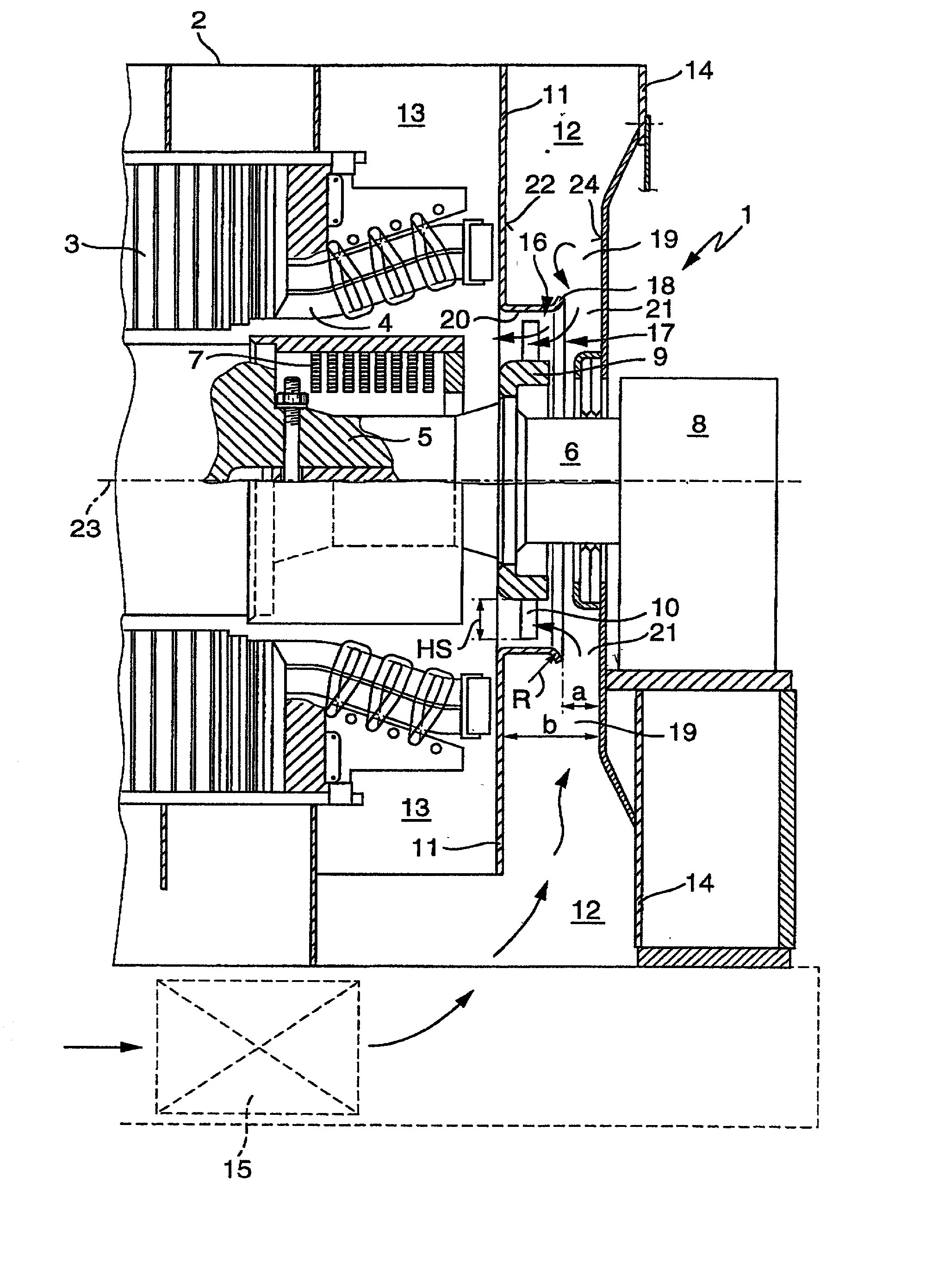
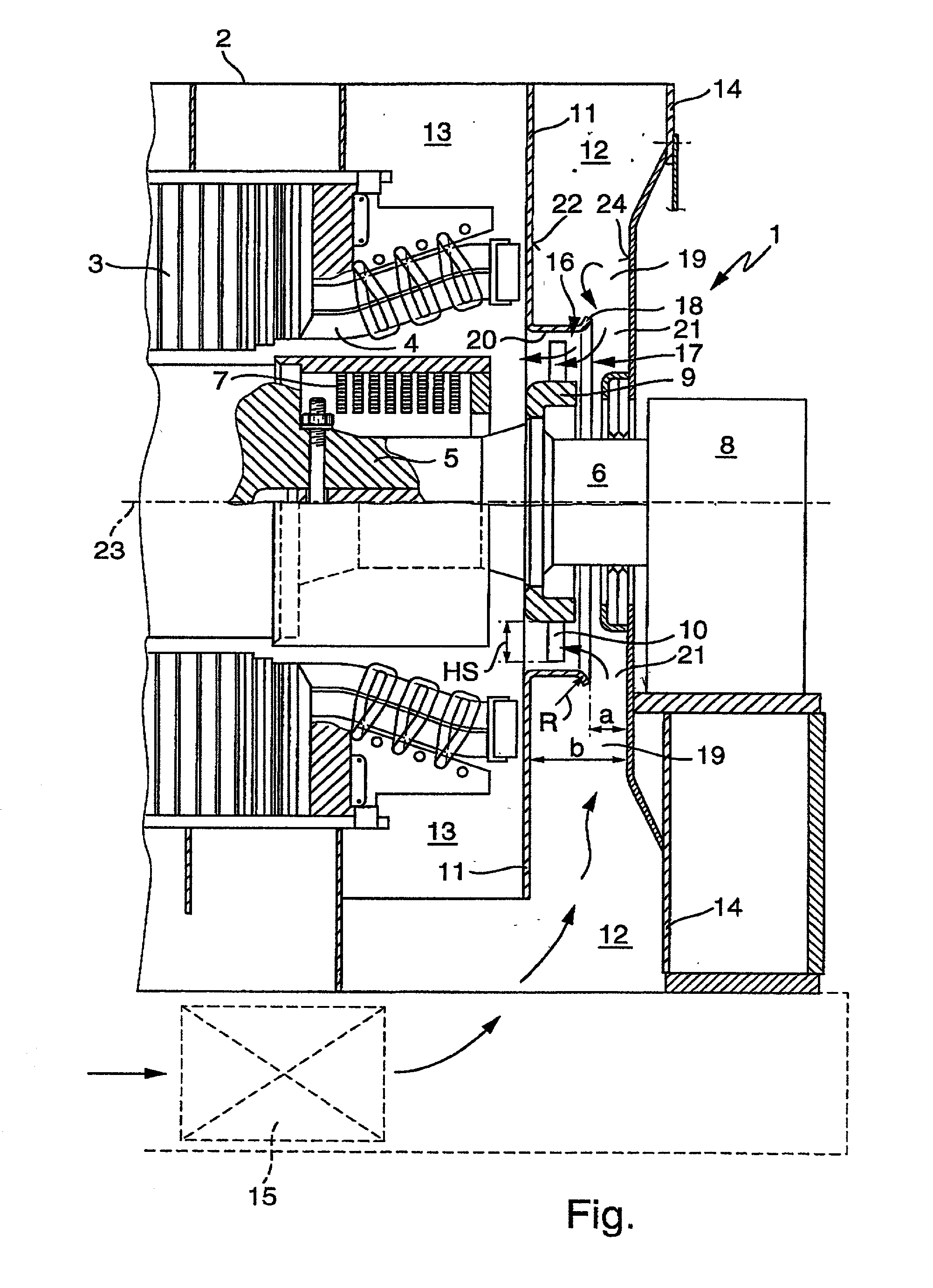
[0005] The invention is based on the general idea of realizing a radial throttling gap by way of a special design of the inflow chamber in the area of an inflow opening of the channel segment directly at the inflow opening, which throttling gap extends, in particular rotation-symmetrically, along the entire inflow opening. Since the throttling effect of a throttling point depends on the pressure conditions present, higher inflow speeds are reduced to a greater degree than lower inflow speeds. The pressure conditions and the flow speeds along the throttling gap, and therefore along the inflow opening, are therefore homogenized. Overall, the blades of the axial ventilator therefore can be supplied more evenly with the inflowing cooling gas, so that the cooling effect within the machine, and therefore its utilization, can be improved. This conversion of the asymmetrical cooling gas supply that flows into the inflow chamber to a symmetrical cooling gas flow towards the axial ventilator is achieved with relatively simple constructive means, so that the invention can be realized at a relatively low cost.
[0006] In a special embodiment, the annular collar set into the annular chamber can be formed by the channel segment itself or by a portion of the channel segment. This design therefore does not require any additional components that must be installed into the machine in order to realize the machine according to the invention.

Problems solved by technology

Under these conditions, different air speeds occur in the outflow chamber, resulting in an uneven cooling effect.
However, poor cooling has a detrimental effect on the utilization of the machine.
However, the production and installation of such a gas guidance element is relatively complicated and expensive.

Method used


Image

  • Gas-cooled machine, in particular a turbo-generator
  • Gas-cooled machine, in particular a turbo-generator

Examples


Embodiment Construction

[0013] According to the only figure, a gas-cooled, electrical machine 1 according to the invention may be formed preferably by a turbo-generator, of which only an end part is shown. A stator 3 of the turbo-generator 1, which is provided in the usual manner with stator windings 4, is positioned in a housing 2. A rotor 5 of the turbo-generator 1 has a shaft 6, on which a rotor winding 7 also is provided in the usual manner. The shaft 6 is positioned at each of its ends in a bearing 8. On this shaft 6, an axial ventilator 9 having axial blades is attached in a non-rotating manner. The radial length of the blades 10 of the axial ventilator 9, i.e. the blade height, is hereby designated with HS. A cover 11, which, in particular, may be constructed in several parts, divides an inflow chamber 12 of the axial ventilator 9 from an outflow chamber 13. The inflow chamber 12 is closed off towards the outside with a corresponding outer cover 14, that also can be constructed in several parts.

[001...


PUM


Abstract

The invention relates to a gas-cooled machine, in particular a turbo-generator, comprising a shaft, on which is positioned an axial ventilator, a cover that divides an inflow chamber for a cooling gas transported by the axial ventilator from an outflow chamber for this cooling gas, and a cylindrical channel segment that is positioned coaxially to the axial compressor and surrounds the axial compressor radially, whereby the inflow chamber comprises an asymmetrical cooling gas supply, and whereby in the inflow chamber means for homogenizing the cooling gas supply to the axial ventilator are provided. In order to improve the cooling, and therefore the efficiency of the machine, the inflow chamber forms a rotation-symmetrical annular chamber in the region of an inflow opening of the channel segment. A cylindrical annular collar is positioned coaxially to the axial ventilator within this annular chamber. The annular collar projects axially into the annular chamber and forms a completely surrounding, radial throttling gap at the inflow opening.

Description

FIELD OF THE INVENTION[0001] The invention relates to a gas-cooled machine, in particular an electrical machine, for example a turbo-generator.BACKGROUND OF THE INVENTION[0002] EP 0 544 023 B1 discloses a gas-cooled, electrical machine of this type that comprises a rotatably drivable shaft, on which is positioned an axial ventilator. The known machine also has a cover that divides an inflow chamber from an outflow chamber. In addition, a cylindrical channel section that is positioned coaxially to the axial ventilator and surrounds the latter radially is constructed on this cover. In particular in gas-cooled turbo-generators, a cooling is ensured by means of axial ventilators that usually are attached on both sides of the turbo-generator rotor shaft and provide the required cooling gas amount and a sufficient pressure level. In such turbo-generators, cooling gas guides are constructed in front of and behind the axial ventilator, said cooling gas guides creating in connection with giv...

Claims


Application Information

Patent Timeline
IPC IPC(8): H02K9/06H02K9/18H02K9/10
CPCH02K9/10
Inventor BAER, JUERGENEICHIN, HERMANN
Owner ALSTOM TECH LTD
Learn More