
Method, system, and program for monitoring system components

a monitoring system and component technology, applied in the field of monitoring system components, can solve problems such as system generation of excessive notifications

Inactive Publication Date: 2002-08-29
ORACLE INT CORP
View PDF10 Cites 89 Cited by
  • Summary
  • Abstract
  • Description
  • Claims
  • Application Information

AI Technical Summary

Benefits of technology

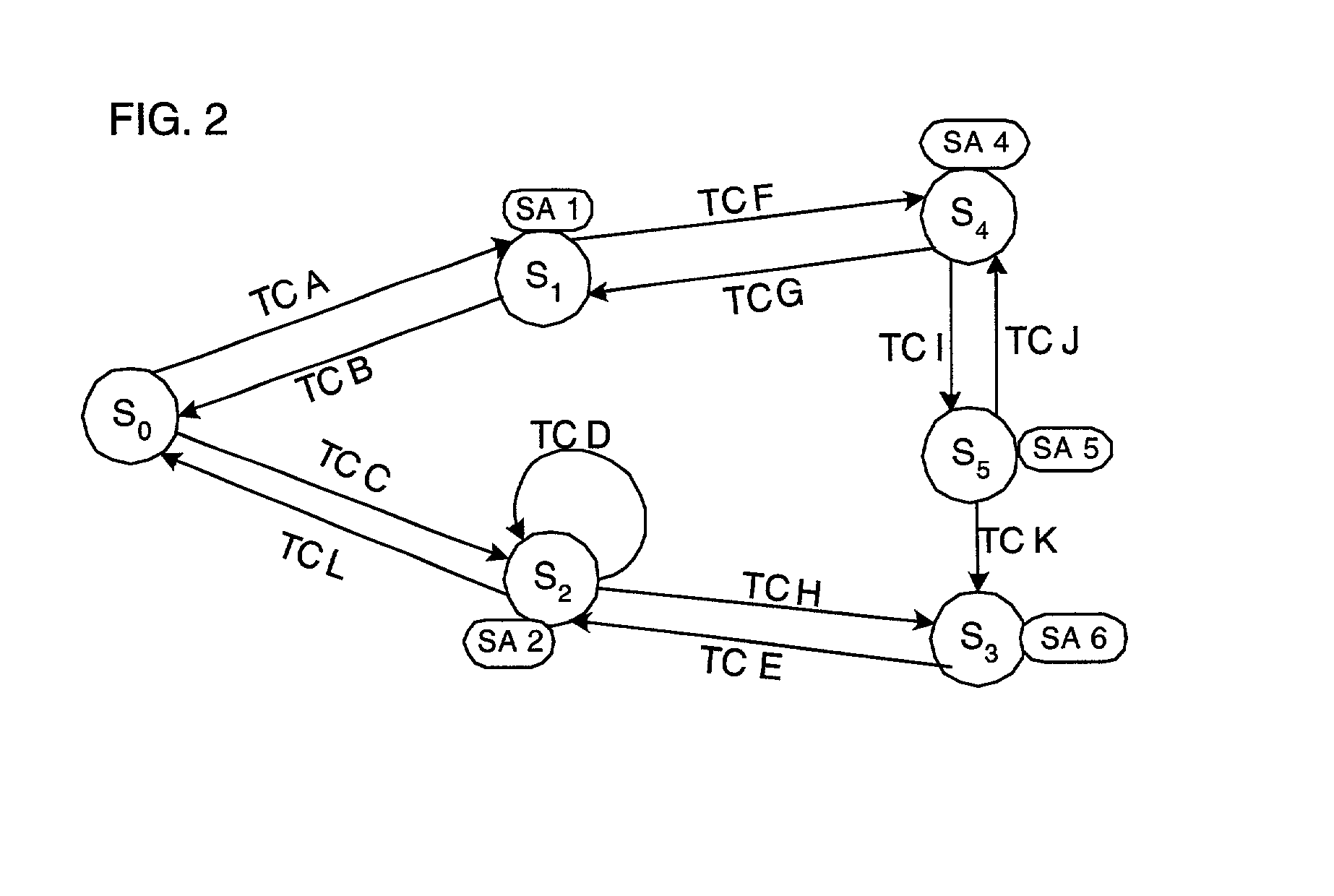
[0056] FIG. 6 illustrates an example of a state machine used to provide notification to an administrator in the event of temperature changes of a monitored system component. From the initial state S.sub.0, when the temperature initially is above 30.degree. Celsius, control proceeds to state S.sub.1 where a yellow alarm notification is generated. The notification may display an alert on an administrator's computer monitor or generate an e-mail or pager notification. If a subsequent temperature measurement is above 60.degree., then the state changes to state S.sub.2 where a "red alert" notification is issued indicating a dangerously high temperature for the monitored system component. If at state S.sub.2 a measured temperature falls below 50.degree., then control proceeds to intermediate state S.sub.3 where a counter is incremented. Subsequent temperature measurements between 30.degree. and 60.degree. while at state S.sub.3 increments the counter without any notification to the user. State S.sub.3 is an intermediate state that prevents the state machine from issuing continuous notifications if the temperature is constantly fluctuating in a range. Instead, at state S.sub.3, a notification may be issued providing information on the counter, i.e., the number of times the temperature was between 30.degree. and 60.degree., after a time interval from the last notification or if the counter reaches a maximum value. In this way, the state machine of FIG. 6 provides intelligence in determining whether to take an action based on a monitored system value because the intermediate state S.sub.3 prevents constant notifications if the temperature is continually fluctuating to avoid overloading the system administrator with unnecessary notifications.

Problems solved by technology

Such systems may generate excessive notifications if system resource values are experiencing thrashing, i.e., constantly changing and thereby constantly triggering alarms as the state change passes the threshold value.

Method used


Image

  • Method, system, and program for monitoring system components
  • Method, system, and program for monitoring system components
  • Method, system, and program for monitoring system components

Examples


Embodiment Construction

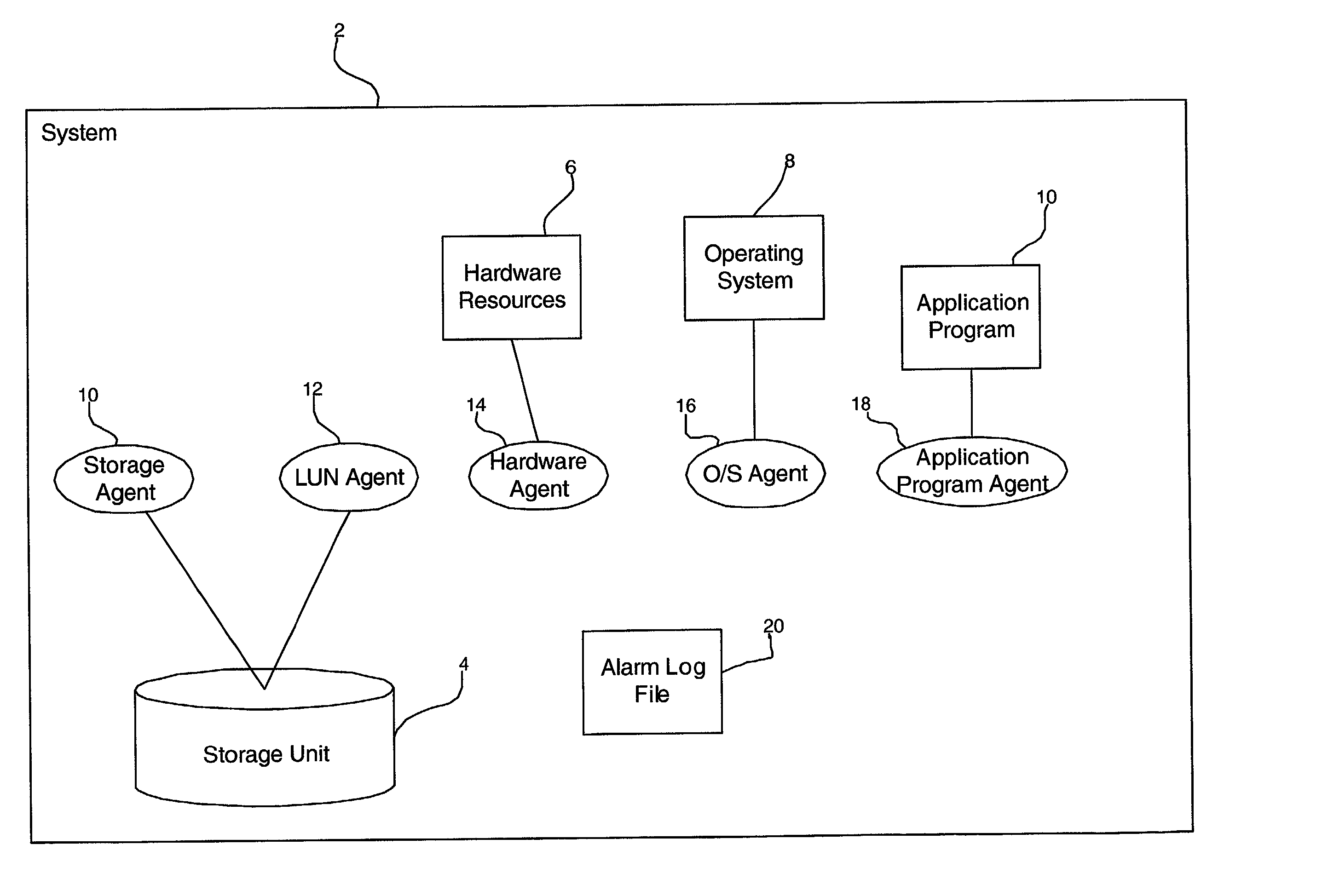
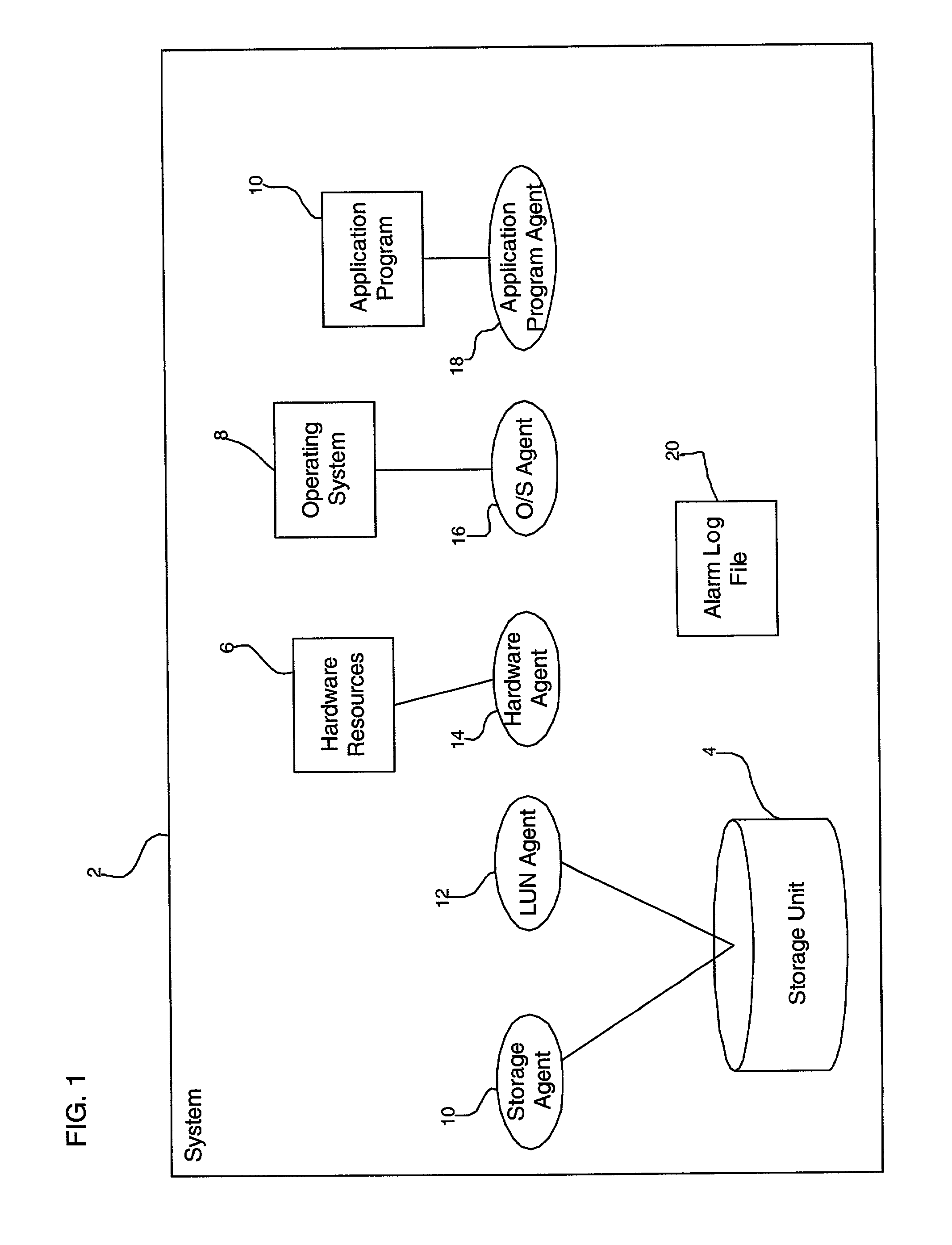
[0008] Provided is a method, system, program, and data structure for deriving state information concerning a monitored system component A status object is provided including information on a current state of the monitored system component. There are a plurality of states associated with the monitored system component, wherein each state is capable of having a state action and at least one transition condition associated with a transition state. A measured system parameter is received and a determination is made as to whether the received measured system parameter satisfies one transition condition associated with the current state indicated in the status object. If the received system parameter satisfies one transition condition, then the state action associated with the transition state associated with the satisfied transition condition is performed. The current state is set to the transition state in the status object.

[0009] In further implementations, if the transition state asso...


PUM


Abstract

Provided is a method, system, program, and data structure for deriving state information concerning a monitored system component. A status object is provided including information on a current state of the monitored system component. There are a plurality of states associated with the monitored system component, wherein each state is capable of having a state action and at least one transition condition associated with a transition state. A measured system parameter is received and a determination is made as to whether the received measured system parameter satisfies one transition condition associated with the current state indicated in the status object. If the received system parameter satisfies one transition condition, then the state action associated with the transition state associated with the satisfied transition condition is performed. The current state is set to the transition state in the status object.

Description

[0001] 1. Field of the Invention[0002] The present invention relates to a method, system, and program for monitoring system components.[0003] 2. Description of the Related Art[0004] Prior art devices provide a monitoring program to monitor the operation of a system. For instance, the Sun Microsystems, Inc. ("SUN") StorEdge Enclosure Manager provides management and monitoring of a SUN A5x00 storage subsystem.** The StorEdge Enclosure Manager provides alarm notification and remote reporting (via email, files, and system logging) upon detection of abnormal activities or conditions within a designated storage enclosure. An alarm provides a notification that signifies that a problem may need to be resolved depending on a detected severity. The StorEdge Enclosure Manager monitors system status information in intervals as part of a "polling" operation. In monitoring specific hardware components, a set of "rules" are provided that define the conditions under which a notification or alarm is...

Claims


Application Information

Patent Timeline
Patent Type & Authority Applications(United States)
IPC IPC(8): G06F11/32
CPCG06F11/328
Inventor NGUYEN, TIN L.SELIM, DINA H.
Owner ORACLE INT CORP
Learn More