
Copolymerization of reactive silicone and urethane precursors for use in conductive, soft urethane rollers

a technology of reactive silicone and reactive urethane, which is applied in the direction of portable power-driven tools, instruments, and discharge of corona, can solve the problems of high cost, low production, and difficulty in coating a charge roller of high conductivity and soft durometer with one layer of rubber/foam (specifically urethane), and achieves low tackiness. the effect of good resistance to chang

Inactive Publication Date: 2002-08-15
FLEET NAT BANK
View PDF0 Cites 9 Cited by
  • Summary
  • Abstract
  • Description
  • Claims
  • Application Information

AI Technical Summary

Benefits of technology

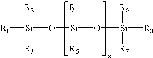
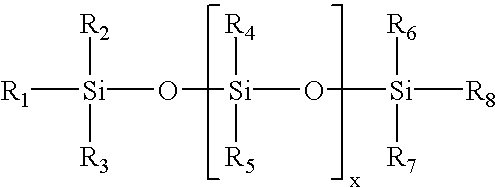
[0009] In one aspect, the conductive roller contains a metal salt evenly or homogeneously distributed in a copolymer formed of the precursors: (i) a diisocyanate, (ii) a reactive silicone containing an amine group, and (iii) a polyol or a polyamine. The incorporation of silicone into the backbone of the copolymer generally allows the resulting copolymer to have low tackiness property and better resistance to change in humidity and temperature. The roller preferably is substantially free of plasticizer and non-reactive silicone oil. As used herein, a copolymer that is "substantially free" of a material means that the amount of the material is negligible in the composition, i.e., less than about 0.001 wt % of the total weight of the copolymer. By "non-reactive" is meant the silicone oil does not incorporate into the backbone of the copolymer.
[0020] A urethane linkage (--NH--C(.dbd.O)--O--) results when a hydroxyl group of the reactive silicone precursor reacts with the diisocyanate; whereas a urea linkage (--NH--C(.dbd.O)--NH--) results when an amine group of the reactive silicone precursor reacts with the diisocyanate. In general, copolymers containing polyurea displays higher rigidity than those containing polyurethane. The rigidity of the copolymer can be adjusted by the ratio of the number of hydroxyl groups to the number of amino groups present in the silicone precursor. Moreover, as mentioned above, the preferred silicone-containing copolymers have better resistance towards changes in humidity.

Problems solved by technology

Due to the need to coat the surface with multiple layers, low production and high cost result.
Coating a charge roller of high conductivity and soft durometer with one layer of rubber / foam (specifically, urethane) has been a challenging task.
The use of plasticizer, however, may lead to tackiness on the surface of the roller, which can result in poor print quality.
When the hardness drops to below 50 Shore A, the surface of the roller can become too tacky for the toner powder to be properly transferred from the developer roller to the drum, resulting in poor print quality.
On the other hand, a hardness of more than 50 Shore A may lead to partial melting of the toner for high speed, high resolution printers.

Method used


Image

  • Copolymerization of reactive silicone and urethane precursors for use in conductive, soft urethane rollers
  • Copolymerization of reactive silicone and urethane precursors for use in conductive, soft urethane rollers
  • Copolymerization of reactive silicone and urethane precursors for use in conductive, soft urethane rollers

Examples


examples 2-8

[0046] Charge rollers described in the following examples were prepared using the same general procedure used in Example 1. The following tables provide the amount (in parts) of each ingredient in the thermoset copolymer:

3 Stream Ex. 2 Ex. 3 Ex. 4 Ex. 5 Ex. 6 Ex. 7 Ex. 8 B1 100.0 100.0 100.0 100.0 100.0 100.0 100.0 (I-2143L) A 437.3 396.7 548.6 419.2 480.5 477.1 475.3 Conductive curative B2 400.0 -- -- 503.5 312.0 312.0 312.0 (GP-145 / HP-6500T) B2 -- 334.3 322.4 -- ---- --(GP-145 / P-380)

[0047] Listed below is the composition of conductive curative (stream A) in each of Examples 2-8:

4 Composition Ex. 2 Ex. 3 Ex. 4 Ex. 5 Ex. 6 Ex. 7 Ex. 8 HP-6500T 325.9 -- -- 350.0 325.9 325.9 325.9 P-380 -- 250.0 450.0 -- -- -- --Poly BD 24.0 24.0 24.0 24.0 24.0 24.0 24.0 (20LM) TIPA 1.5 1.5 1.5 1.5 1.5 1.5 1.5 XB 11.5 11.5 11.5 11.5 11.5 11.5 11.5 Lithium 1.0 5.4 7.4 8.5 10.0 13.0 14.0 perchlorate (anhy.) Iron (III) -- -- -- ---- -- 9 chloride T-328 12.0 12.0 12.0 12.0 12.0 12.0 12.0 BHT 3.5 3.5 3.5 3...

examples 9-14

[0050] Developer rollers described in the following examples were prepared using the same general procedure used in Example 1. The following tables provide the amount (in parts) of each ingredient in the thermo set copolymer:

7 Stream Temp. Ex. 9 Ex. 10 Ex. 11 Ex. 12 Ex. 13 Ex. 14 B1 180.degree. F. 100.0 100.0 100.0 100.0 100.0 100.0 (V-6020; NCO = 6.85) A 150.degree. F. 24.7 21.7 21.8 21.8 21.8 21.8 Conductive curative B2 90.degree. F. 165.6 172.2 173.0 173.0 173.0 173.0 (GP-145 / HP-6500T)

[0051] Listed below is the composition of conductive curative (stream A) in each of Examples 9-14:

8 Composition Ex. 9 Ex. 10 Ex. 11 Ex. 12 Ex. 13 Ex. 14 HP-6500T 250.0 200.0 200.0 200.0 200.0 200.0 T-1000 20.0 20.0 20.0 20.0 20.0 20.0 TIPA 20.0 20.0 20.0 20.0 20.0 20.0 I-93 80.0 80.0 80.0 80.0 80.0 80.0 Iron (III) 0.56 0.08 0.14 0.20 -- --chloride Copper (II) 0.07 0.01 0.02 --0.25 --chloride Lithium 0.07 0.01 0.02 -- -- 0.22 perchlorate (anhy.) T-328 6.0 6.0 6.0 6.0 6.0 6.0 BHT 3.0 3.0 3.0 3.0 3.0 3...


PUM

PropertyMeasurementUnit
temperatureaaaaaaaaaa
humidityaaaaaaaaaa
temperatureaaaaaaaaaa

Abstract

The invention relates to a low tacky, conductive, soft urethane roller for use in a printer. The roller includes a metal salt evenly or homogeneously distributed in a copolymer formed of a diisocyanate, a reactive silicone containing an amine group; and a polyol or a polyamine. The roller can also have a volume resistivity of between about 1E5 ohm-cm and about 5E10 ohm-cm, and includes a metal salt solution in a copolymer formed of a diisocyanate, a reactive silicone containing a hydroxyl group and / or an amine group; and a polyol and / or a polyamine.

Description

[0001] This invention relates to conductive, soft urethane rollers, e.g., developer rollers, charge rollers, or toner transfer rollers, for use in an electrophotographic printer, e.g., a laser printer. The invention also relates to an electrophotographic printer containing such a roller.[0002] A laser printer often includes a digital light emitter photoconductor drum, a charge roller, a developer roller, a developer blade, a transfer roller, and a toner storage unit. During printing, the transfer roller supplies toner to the developer roller, and the developer blade forms the toner into a thin, even layer on the surface of the developer roller. The charge roller, which is in contact with the surface of the photoconductive drum, receives a high voltage from a power supply, and charges the photoconductive drum with a positive or negative charge. After the photoconductive drum has been exposed a light emitter, the surface of the photoconductor drum forms an electrostatic latent image. ...

Claims


Application Information

Patent Timeline
Patent Type & Authority Applications(United States)
IPC IPC(8): C08K3/16
CPCC08K3/16C08L75/04Y10T428/31663
Inventor CHIANG, ALBERT C.RODERICK, JOHN A.
Owner FLEET NAT BANK
Learn More