
Self-assembled near-zero-thickness molecular layers as diffusion barriers for Cu metallization

Inactive Publication Date: 2002-08-08
RENESSELAER POLYTECHNIC INST
View PDF0 Cites 32 Cited by
  • Summary
  • Abstract
  • Description
  • Claims
  • Application Information

AI Technical Summary

Problems solved by technology

There are, however, unresolved issues with its use.
The diffusion, over time, results in junction linkage, which decreases device efficiency.
The formation of these layers, however, uses sophisticated sputtering processes and results in the inclusion of substantial contaminants.

Method used


Image

  • Self-assembled near-zero-thickness molecular layers as diffusion barriers for Cu metallization
  • Self-assembled near-zero-thickness molecular layers as diffusion barriers for Cu metallization
  • Self-assembled near-zero-thickness molecular layers as diffusion barriers for Cu metallization

Examples


Embodiment Construction

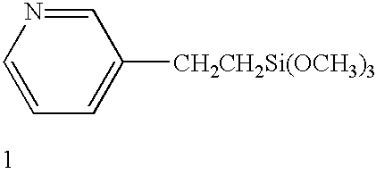
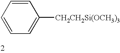
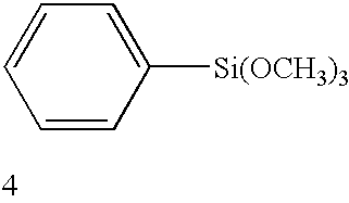
[0016] Devising ultra-thin barrier layers to prevent Cu diffusion into SiO.sub.2-based dielectrics is a major challenge that must be met to increase the speed, number density, and performance of microelectronics devices. Here, we demonstrate the use of near-zero-thickness (<2-nm-thick) self-assembled monolayers (SAMs) as barriers to Cu diffusion into SiO.sub.2. Cu / SiO.sub.2 / Si(001-metal-oxide-semiconductor (MOS) capacitors, with and without SAMs at the Cu / SiO.sub.2 interface, were annealed at 200.degree. C. in a 2 MV cm.sup.-1 electrical field. Capacitance-voltage (C-V) and current-voltage (I-V) measurements of MOS capacitors coated with SAMs having aromatic terminal groups consistently show as much as 5-orders-of-magnitude lower leakage currents and a factor-of-4 higher time to failure when compared with the corresponding values from uncoated interfaces. SAMs with short tail lengths or aliphatic terminal groups are ineffective in hindering Cu diffusion, indicating that the molecula...


PUM


Abstract

The present invention provides a diffusion barrier in an integrated circuit. The diffusion barrier comprises a self-assembled monolayer. The diffusion barrier is preferably less than 5 nm thick; more preferably it is less than 2 nm thick. The self-assembled monolayer typically contains an aromatic group at its terminus.

Description

RELATED CASES[0001] This application is related to and claims priority to provisional Applications Nos. 60 / 240,109 entitled Diffusion Barriers Comprising A Self-Assembled Monolayer naming G. Ramanath, Ahila Krishnamoorthy, Kaushik Chanda and Shyarm P. Murarka as inventors and filed Oct. 12, 2000, 60 / 244,160 entitled Diffusion Barriers Comprising A Self-Assembled Monolayer naming G. Ramanath, Ahila Krishnamoorthy, Kaushik Chanda and Shyarm P. Murarka as inventors and filed Oct. 27, 2000, and 60 / 255,100 entitled Self-Assembled Near-Zero-Thickness Molecular Layers As Diffusion Barriers For Cu Metallization naming G. Ramanath, Ahila Krishnamoorthy, Kaushik Chanda and Shyarm P. Murarka as inventors and filed Dec. 12, 2000. These applications are incorporated herein for all purposes as if set forth herein in full.STATEMENT AS TO RIGHTS TO INVENTIONS MADE UNDER FEDERALLY SPONSORED RESEARCH OR DEVELOPMENT[0002] The US Government may have certain rights in this invention pursuant to National...

Claims


Application Information

Patent Timeline
IPC IPC(8): H01L21/312H01L21/768H01L23/532
CPCB82Y10/00B82Y30/00H01L21/3121H01L21/76829H01L23/53228H01L23/53295H01L2924/0002H01L21/02126H01L2924/00
Inventor RAMANATH, G.KRISHNAMOORTHY, AHILACHANDA, KAUSHIKMURARKA, SHYAM P.
Owner RENESSELAER POLYTECHNIC INST
Learn More