
Measurment system and method

a measurement system and measurement method technology, applied in the field of fluid measurement, can solve the problems of increasing the potential for a blowout, reducing the hydrostatic pressure, and affecting the flow rate of the system,

Inactive Publication Date: 2002-08-01
NASA
View PDF0 Cites 78 Cited by
  • Summary
  • Abstract
  • Description
  • Claims
  • Application Information

AI Technical Summary

Benefits of technology

[0027] An advantage of the present invention is a real time system that permits evaluation of fluid flow for early warning of circulation problems when used in drilling operations.
[0028] These and other objects, features, and advantages of the present invention will become apparent from the drawings, the descriptions given herein, and the appended claims. It will be understood that above-listed objects, features, and advantages of the invention are intended only as an aid in quickly understanding aspects of the invention, are not intended to limit the invention or invention definition in any way, and do not form a comprehensive list of such objects, features, and advantages.
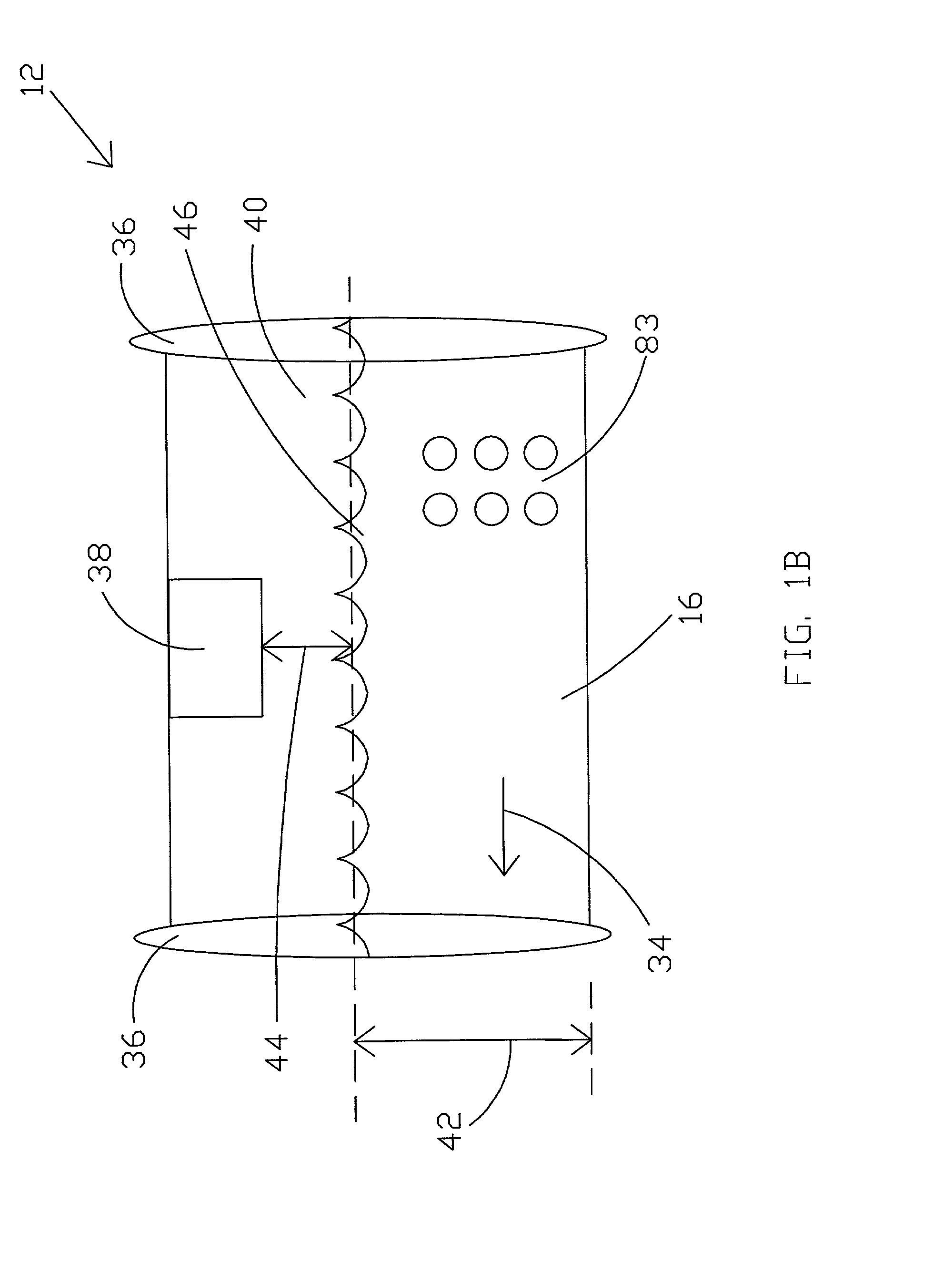
[0029] Therefore, one embodiment of the present invention comprises a fluid measurement system for a fluid comprising one or more system elements such as, for instance, a detector section defining a fluid channel for receiving the fluid, a sonic detector mounted to the detector section with respect to the fluid channel for transmitting an acoustic signal towards a fluid surface of the fluid within the fluid channel and for receiving an acoustic signal reflection from the fluid surface, and a microwave detector mounted to the detector section with respect to the fluid channel so as to be operable for transmitting a microwave signal towards the fluid surface and receiving a microwave signal reflection from the fluid surface. Thus, the inventive configuration very accurately determines the height of the fluids within the detector section on an instantaneous basis.
[0030] Other elements of the system may comprise an instrument section operable for determining a first approximate fluid level of the fluid surface with respect to the fluid channel from the acoustic signal reflection and for determining a second more accurate fluid level of the fluid surface from the first approximate fluid level and the microwave signal reflection. The instrument section may be operable for determining a fluid flow rate of the fluid through the channel from a fluid level of the fluid surface within the fluid channel. In one preferred embodiment, the instrument section is operable for determining the fluid flow rate solely from the fluid level within the fluid channel. In another embodiment, the instrument section detects a phase difference between the transmitted acoustic signal and the received acoustic signal, and the instrument section is operable for determining a fluid density of the fluid from the phase difference.
[0031] The system may further comprise a plurality of acoustic sensors mounted to the detector section in communication with the fluid channel. A transmitter acoustic sensor may be provided for producing a transmitted acoustic signal and a receiver acoustic sensor for receiving a received acoustic signal. This configuration can also determine the fluid density at different layers (heights) within the fluid. Multiple transmitter / receiver pairs, each operating at slightly different frequencies may be used to measure the fluid density at different heights through the fluid.
[0032] Another embodiment of the invention may comprise a detector section defining a fluid channel for receiving the fluid, at least one acoustic signal transmitter mounted to the detector section in communication with the fluid channel for transmitting an acoustic signal through the fluid, at least one acoustic signal receiver mounted to the detector section in communication with the fluid channel operable for receiving the acoustic signal from the acoustic signal transmitter, and at least one instrument section for determining a density of the fluid from a phase change of the acoustic signal between the acoustic signal transmitter and acoustic signal receiver.

Problems solved by technology

However, due to various conditions downhole, problems may occur with the circulation.
For instance, drilling may occur into a lost circulation zone whereby the lost circulation zone, such as a downhole cavern, absorbs a portion of the drilling fluid, thereby reducing the hydrostatic pressure and increasing the potential for a blowout.
As another example, drilling may occur into an unanticipated high pressure zone whereby gas bubbles begin to push the drilling fluid out of the wellbore at a higher rate than fluid is pumped into the wellbore thereby reducing the hydrostatic pressure and increasing the potential for a blowout.
The above prior art does not disclose a system that provides a highly accurate instantaneous mass determination that may be used for comparing circulation input to the wellbore with the circulation output from the wellbore.
Moreover, the prior art does not disclose an inexpensive system for determining densities, volumes, and other measurements of materials such as fluid and water at different positions within a container.
However, there can be 2.pi. phase ambiguities, i.e., the number of complete cycles of the transmit signal is unknown.
The measurement accuracy of the microwave signal is much greater than the measurement accuracy of the acoustic signal, but due to the short wavelength of the microwave signal, there can be many 2.pi. phase ambiguities for the microwave signal.
It is well known that in zero gravity environments, cryogenic fluids tend to flow in globs inside the tanks, making it almost impossible to make measurements as to the amount of fuel remaining in the tank.
These anomalies or lumps in the propellant tube can cause non-uniform firing of the propellant.

Method used


Image

  • Measurment system and method
  • Measurment system and method
  • Measurment system and method

Examples


Embodiment Construction

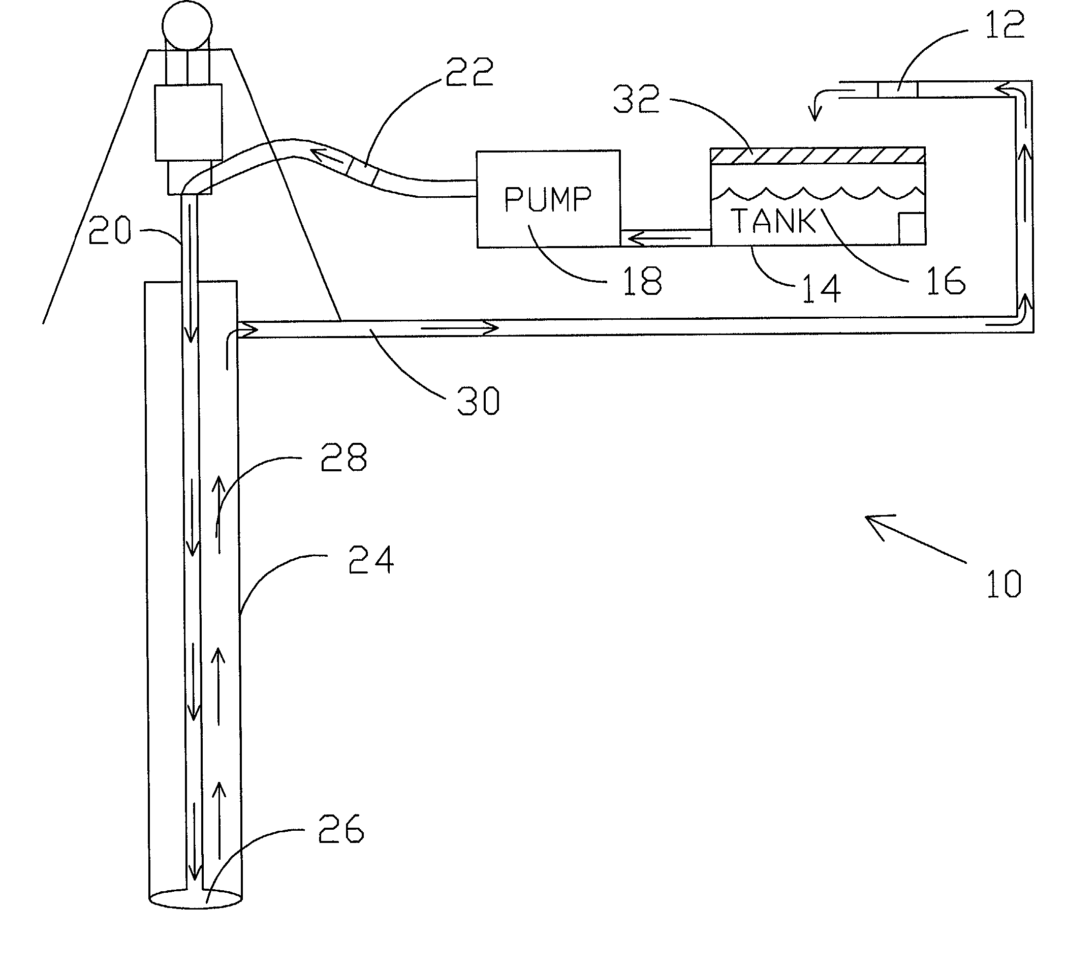
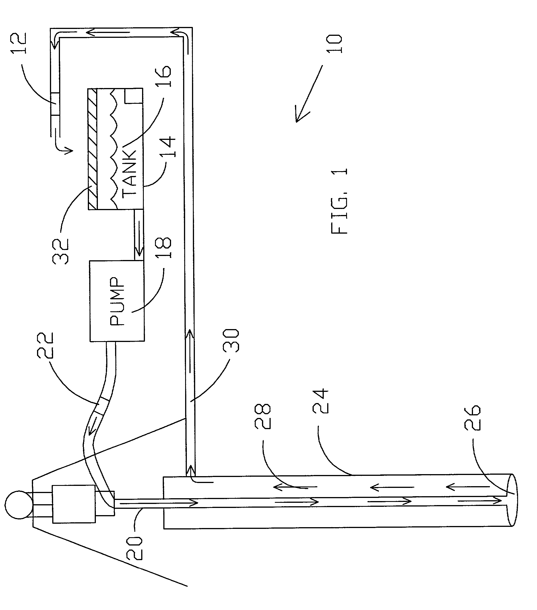
[0061] In one presently preferred embodiment of the invention, a primary object of a mass measuring system is to measure the entrance and the exit masses of drilling fluid while drilling a well hole. After the input mass of the fluid is determined, the added or lost mass at the exit reveals the mass being generated or lost during drilling. This should provide early warning of trouble during the drilling process and possibly avoid the loss of a hole.

[0062] The present invention provides a sensing system that can provide accurate volume and density measurements of drilling fluid in one or more locations of the drilling fluid circulation stream as the drilling fluid is circulated into and out of the wellbore during drilling operations. To determine mass flow, the present invention preferably determines fluid velocity and density and then calculates instantaneous mass flow and / or mass flow over a selected time period. In one preferred embodiment of the invention, the entire fluid flow i...


PUM


Abstract

System and methods are disclosed for fluid measurements which may be utilized to determine mass flow rates such as instantaneous mass flow of a fluid stream. In a preferred embodiment, the present invention may be utilized to compare an input mass flow to an output mass flow of a drilling fluid circulation stream. In one embodiment, a fluid flow rate is determined by utilizing a microwave detector in combination with an acoustic sensor. The acoustic signal is utilized to eliminate 2 pi phase ambiguities in a reflected microwave signal. In another embodiment, a fluid flow rate may be determined by detecting a phase shift of an acoustic signal across two different predetermined transmission paths. A fluid density may be determined by detecting a calibrated phase shift of an acoustic signal through the fluid. In another embodiment, a second acoustic signal may be transmitted through the fluid to define a particular 2pi phase range which defines the phase shift. The present invention may comprise multiple transmitters / receivers operating at different frequencies to measure instantaneous fuel levels of cryogenic fuels within containers positioned in zero or near zero gravity environments. In one embodiment, a moveable flexible collar of transmitter / receivers may be utilized to determine inhomogenuities within solid rocket fuel tubes.

Description

[0002] 1. Field of the Invention[0003] The present invention relates generally to fluid measurements and, more specifically, to a fluid measurement system that may be utilized for making mass measurements during fluid flow. The present invention also has application in reduced and zero gravity environments and for finding discontinuities in an otherwise homogeneous material.[0004] 2. Background of the Invention[0005] It is well known that when drilling wells for hydrocarbons, a standard drilling practice involves circulating drilling fluid from the surface downwardly through the drilling string. The drilling fluid emerges at the drill bit and returns to the surface through the annulus in the wellbore on the outside of the drilling string. The drilling fluid performs many functions, some of which are discussed herein. The drilling fluid cools and reduces friction of rotating the drilling string. The drilling fluid removes excavated material from the wellbore in the circulation stream...

Claims


Application Information

Patent Timeline
IPC IPC(8): G01F23/284G01F23/296G01F25/00G01S13/10G01S13/86G01S15/10G01S15/58
CPCG01F23/284G01F23/2962G01F25/0061G01S13/10G01S15/101G01S15/584G01S13/862G01F25/20
Inventor ARNDT, G. DICKEYNGO, PHONG H.CARL, JAMES R.BYERLY, KENT A.
Owner NASA
Learn More