
Microcontroller, switched-mode power supply, ballast for operating at least one electric lamp, and method of operating at least one electric lamp

Inactive Publication Date: 2002-07-25
PATENT TREUHAND GESELLSCHAFT FUR ELECTRIC GLUEHLAMPEN MBH
View PDF0 Cites 38 Cited by
  • Summary
  • Abstract
  • Description
  • Claims
  • Application Information

AI Technical Summary

Benefits of technology

[0006] A further object of the invention is to provide a switched-mode power supply provided with a microcontroller with improved driving of the switching means of the switched-mode power supply.
[0026] In order to apply a heating current to the lamp electrodes, the ballast according to the invention advantageously has a heating device equipped with a controllable switching means, and the microcontroller has a comparator, which compares the charge state of the charge store with a reference value for the lamp electrode heating and which is used to generate a control signal for the pulse-width modulation of the controllable switching means of the heating device. As a result, the oscillation of the oscillator mentioned above can be evaluated not only for the purpose of controlling the inverter but additionally for the regulation of the heating current for the lamp electrodes. The reference value for the lamp electrode heating is advantageously adjustable by means of a read / write memory, in order to be able to adapt the heating current for the lamp electrodes to the different operating states of the lamp. The microcontroller additionally advantageously has synchronization means for synchronizing the controllable switching means of the heating device with a switching means of the inverter. As a result, driving the switching means of the heating device is simplified. In addition, the oscillatory behavior of the inverter is influenced positively as a result.
[0029] The two devices for the alternate charging and discharging of a charge store advantageously in each case have a controllable current source for applying an adjustable charging current to the charge store and the second charge store, and in each case a controllable current sink for applying an adjustable discharging current to the charge store and, respectively the second charge store. The controllable current sources and current sinks may be produced in a known manner with the aid of semiconductor technology and integrated into the microcontroller. As a result, the two devices for the alternate charging and discharging of a charge store can be produced with simple means as a constituent part of the microcontroller. In order to ensure fine graduation of the frequency control signals or the pulse-width modulation control signals, the settings of the controllable current sources and current sinks can be varied in relation to a reference current level, in each case with a resolution of at least 8 bits. The aforementioned reference current level for the charging current and the discharging current can advantageously be predefined by means of a nonreactive resistor. This makes it possible to adapt the control of the inverter to different mains voltages by means of appropriate dimensioning of the nonreactive resistor. In order to save components, it is additionally preferable for only a single nonreactive resistor to be used to predefine the same reference current level for the charging and discharging currents of the two charge stores.
[0035] The method according to the invention also permits heating of the lamp electrodes, by the heating current for the lamp electrodes being regulated by means of a controllable switching means. The signals for the pulse-width modulated control of the controllable switching means of the heating device are advantageously generated with the aid of a comparator, which compares the charge state of the charge store with a reference value for the lamp electrode heating. In this way, frequency control signals and / or pulse-width modulation control signals can be generated both for the switching means of the inverter and for the controllable switching means of the heating device, by the duration of the charging and discharging operations of the charge store being evaluated. The reference value for the lamp electrode heating is advantageously set on the basis of the desired heating power and stored in a read / write memory of the microcontroller. As a result, the heating power can be set under program control by means of the microcontroller. In addition, the controllable switching means for regulating the heating current are advantageously switched on synchronously with a switching means of the inverter. This simplifies the driving of the controllable switching means of the heating device. The duty cycle of the controllable switching means for regulating the heating current is preferably smaller than or equal to the duty cycle of the corresponding switching means of the inverter.

Problems solved by technology

However, in this way, using cost-effective microcontrollers, no finely graduated pulse-width modulation control nor any finely graduated frequency control of the inverter can be carried out, since the smallest possible, adjustable change in the pulse width or in the frequency of the control signal which can be generated by the counting mechanism explained above is limited by the operating cycle frequency of the microcontroller and by the memory size of the counting mechanism.
However, for cost reasons, such microcontrollers cannot be used in electronic ballasts for lamp operation.

Method used


Image

  • Microcontroller, switched-mode power supply, ballast for operating at least one electric lamp, and method of operating at least one electric lamp
  • Microcontroller, switched-mode power supply, ballast for operating at least one electric lamp, and method of operating at least one electric lamp
  • Microcontroller, switched-mode power supply, ballast for operating at least one electric lamp, and method of operating at least one electric lamp

Examples


Embodiment Construction

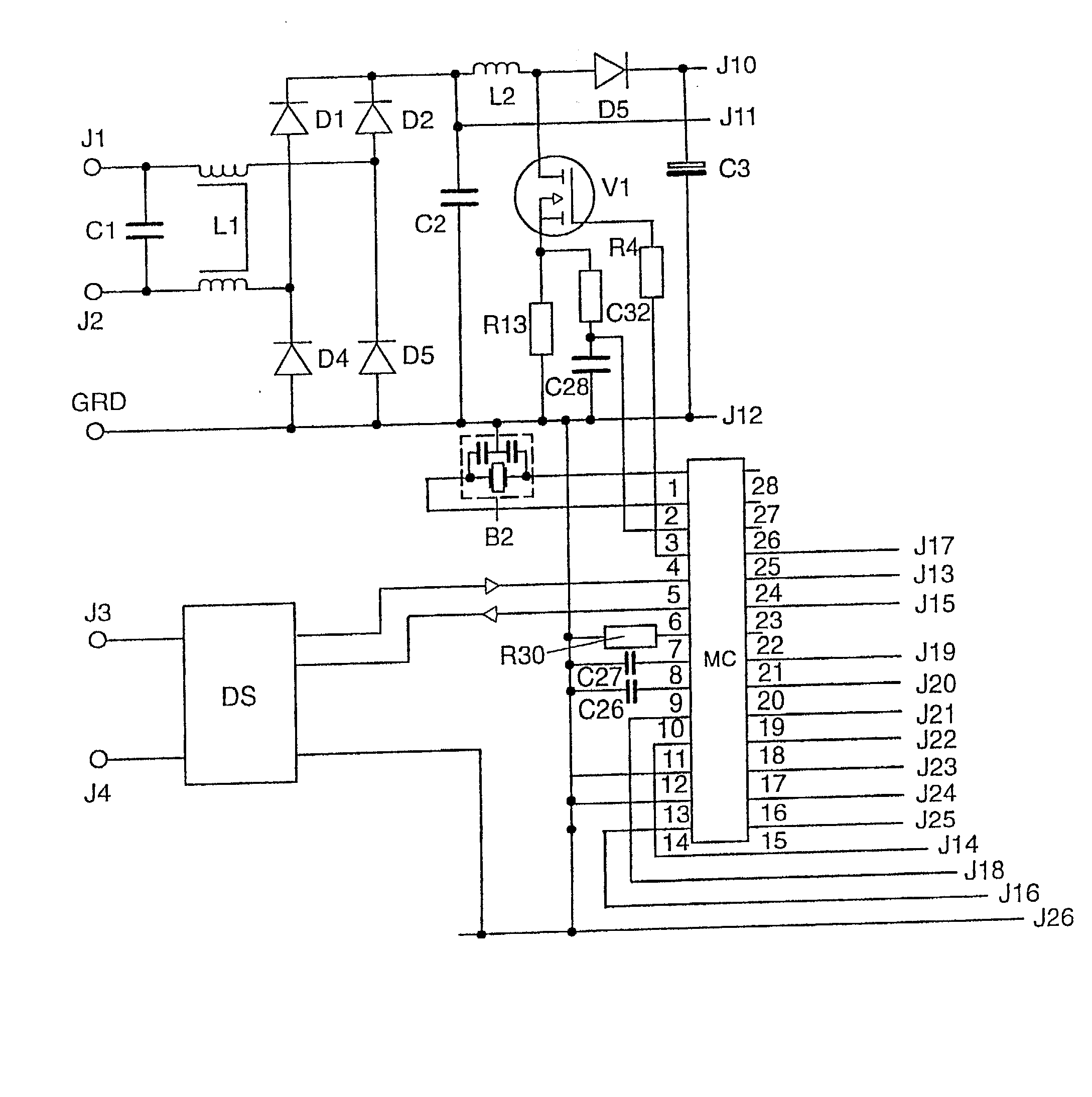
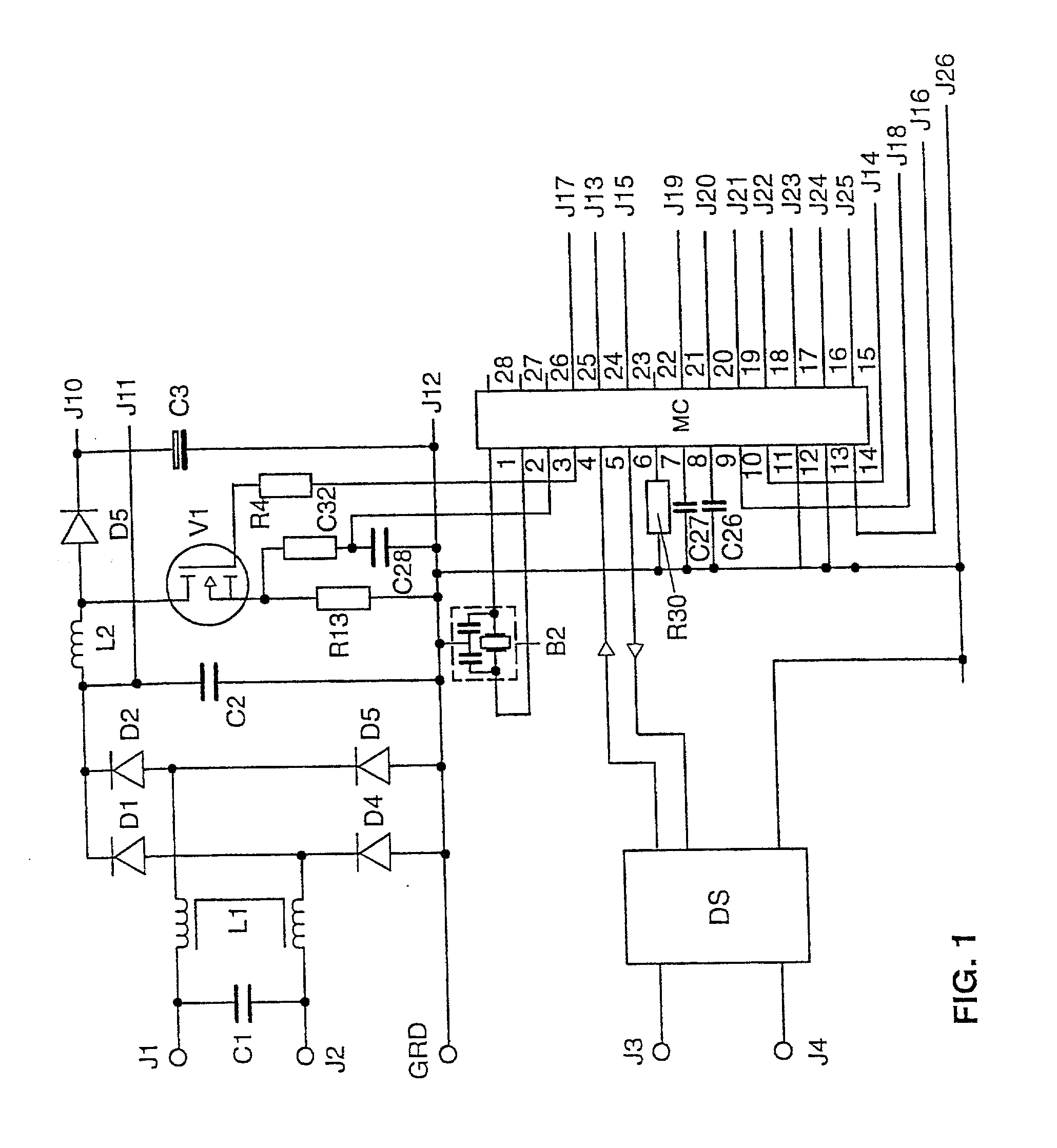
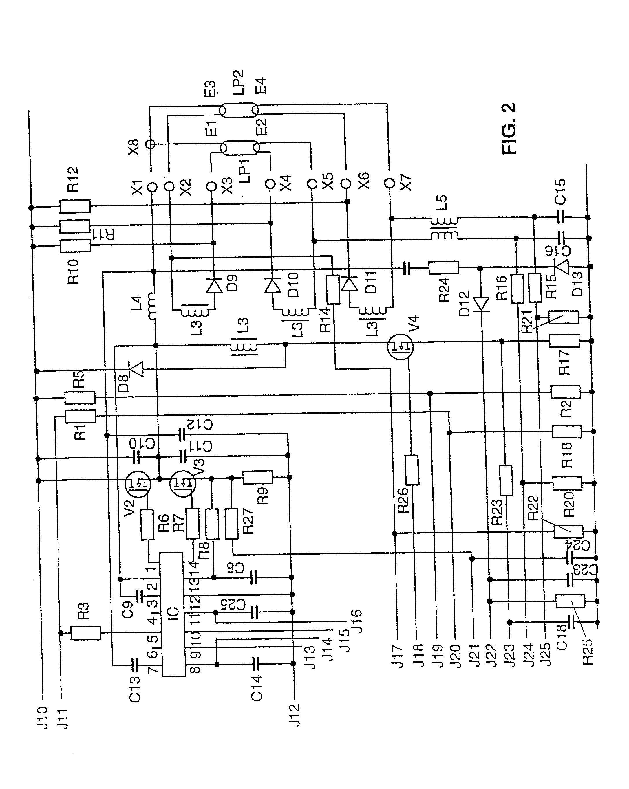
[0038] The invention will be explained in more detail below using a preferred exemplary embodiment. In the drawing:

[0039] FIG. 1 shows a schematic illustration of the first half of the circuit arrangement according to the preferred exemplary embodiment of the ballast according to the invention

[0040] FIG. 2 shows a schematic illustration of the second half of the circuit arrangement according to the preferred exemplary embodiment of the ballast according to the invention

[0041] FIG. 3 shows a block diagram of the microcontroller

[0042] FIG. 4 shows a block diagram of the second control module G for controlling the half-bridge inverter and the heating device

[0043] FIG. 5 shows a graph of the control signals for the inverter and the heating device

[0044] FIG. 6 shows a block diagram of the first control module E for controlling the step-up converter

[0045] FIG. 7 shows a graph of the control signals for the step-up converter

[0046] The circuit arrangement of the preferred exemplary embodime...


PUM


Abstract

The invention relates to a microcontroller (MC) having at least one device (G) for generating pulse-width modulated or frequency modulated control signals for a switched-mode power supply. According to the invention, this device (G) has a device (SQ1, SS1) for the alternate charging and discharging of an electric charge store (C27) that can be connected to the microcontroller (MC), control means for this device (SQ1, SS1) for controlling the charging and discharging operations, and evaluation means in order to evaluate the time periods which are needed for the individual charging and discharging operations; to generate pulse-width modulated or frequency modulated control signals. The microcontroller (MC) according to the invention generates finely graduated, frequency modulated or pulse-width modulated control signals which are independent of the operating cycle frequency of the microcontroller (MC). The invention further relates to a switched-mode power supply having such a microcontroller (MC) and an electronic ballast for operating at least one electric lamp, and also to an operating method for electric lamps. The frequency modulated or pulse-width modulated control signals for the inverter transistors (V2, V3), for the step-up converter transistor (V1) and for the transistor (V4) of the lamp electrode heating device of the ballast are generated directly by the microcontroller (MC).

Description

[0001] The invention relates to a microcontroller according to the preamble of patent claim 1, a switched-mode power supply according to patent claim 10, a ballast for at least one electric lamp according to the preamble of patent claim 11, and a method of operating at least one electric lamp according to the preamble of patent claim 25.I. TECHNICAL FIELD[0002] In particular, the invention relates to a microcontroller which is provided to drive the switching transistors of a switched-mode power supply, to be specific preferably of a switched-mode power supply for operating electric lamps. In the switched-mode power supplies normally used to operate electric lamps, there are normally inverters, in particular half-bridge, full-bridge and push-pull inverters, and also step-up converters and step-down converters. Modern electronic ballasts for operating electric lamps generally have an inverter to produce a high-frequency alternating current for lamp operation and often also have a step...

Claims


Application Information

Patent Timeline
IPC IPC(8): H05B41/392
CPCH05B41/3921
Inventor KRUMMEL, PETER
Owner PATENT TREUHAND GESELLSCHAFT FUR ELECTRIC GLUEHLAMPEN MBH
Learn More