
Magnetic tape device

a tape cassette and magnetic technology, applied in the field of magnetic tape devices, can solve the problems of tape cassette wobbling, increased manufacturing costs, and high manufacturing costs

Inactive Publication Date: 2002-07-18
FUNAI ELECTRIC CO LTD
View PDF0 Cites 2 Cited by
  • Summary
  • Abstract
  • Description
  • Claims
  • Application Information

AI Technical Summary

Problems solved by technology

Thus, unexpected wobbling of the tape cassette is encountered upon its insertion and ejection.
In addition, a great deal of labor and time are required to fix the leaf springs 4d to the projections 4c, so that the manufacturing method is demanding and the manufacturing expenses are increased.

Method used


Image

  • Magnetic tape device
  • Magnetic tape device
  • Magnetic tape device

Examples


Embodiment Construction

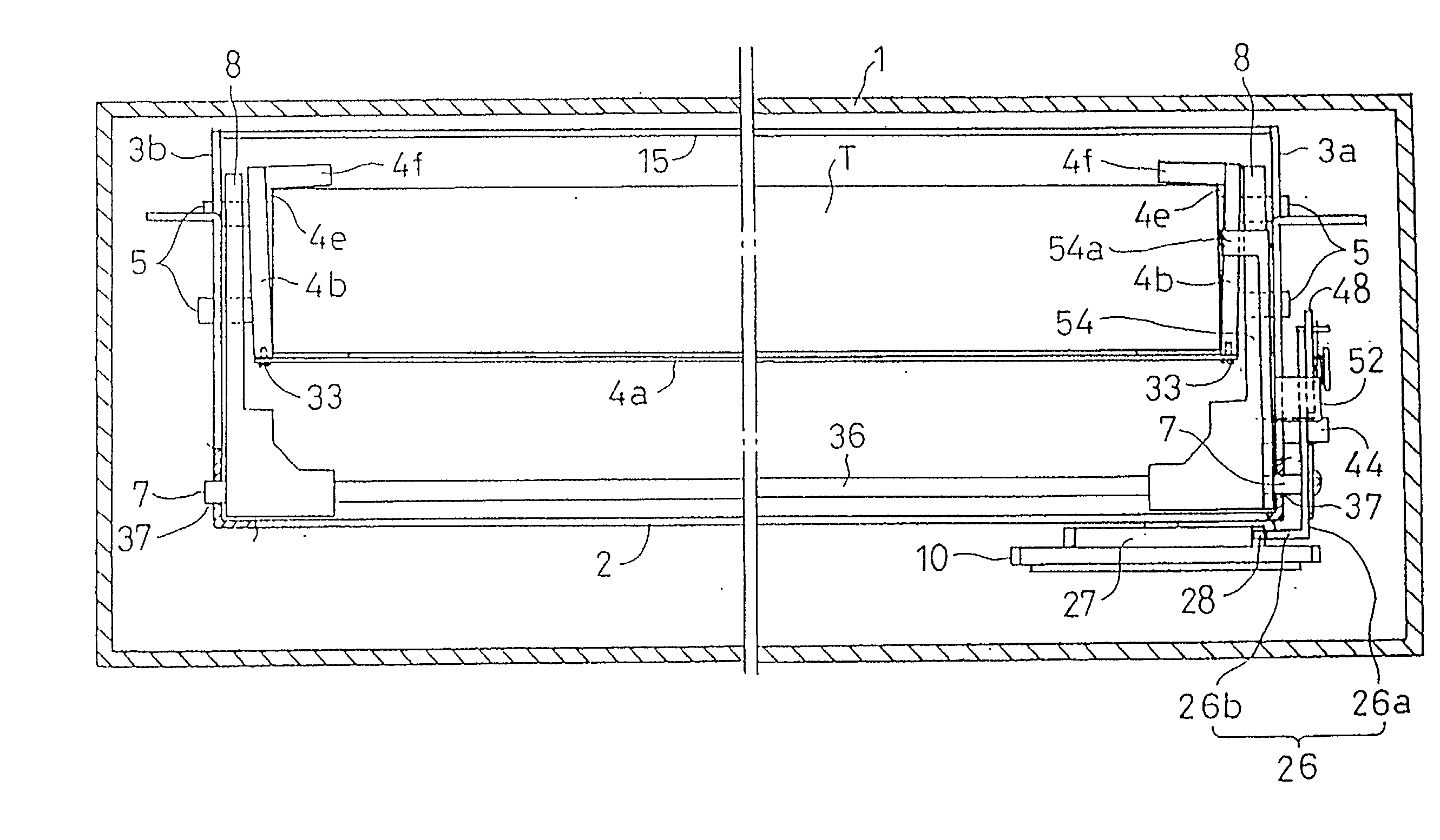
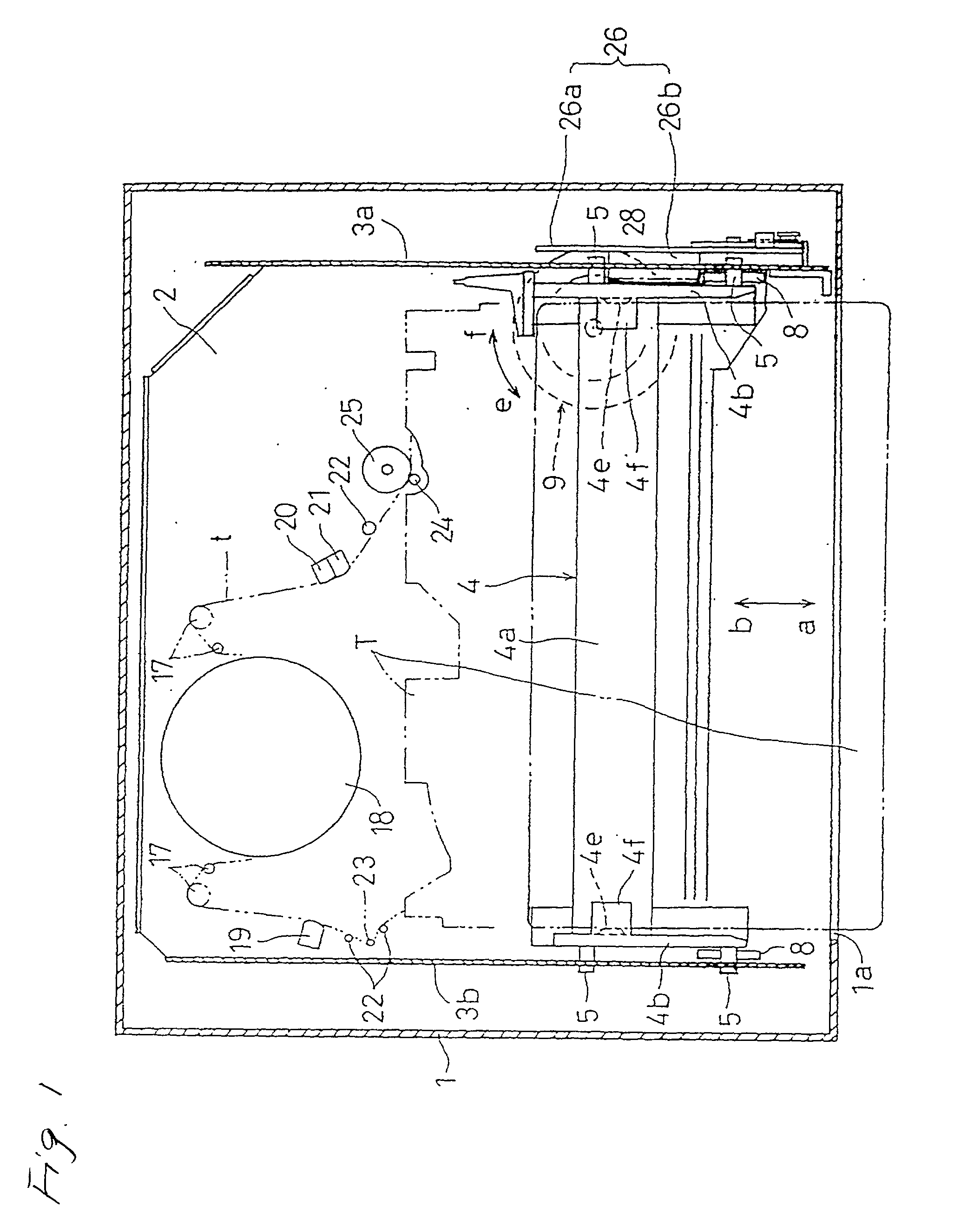
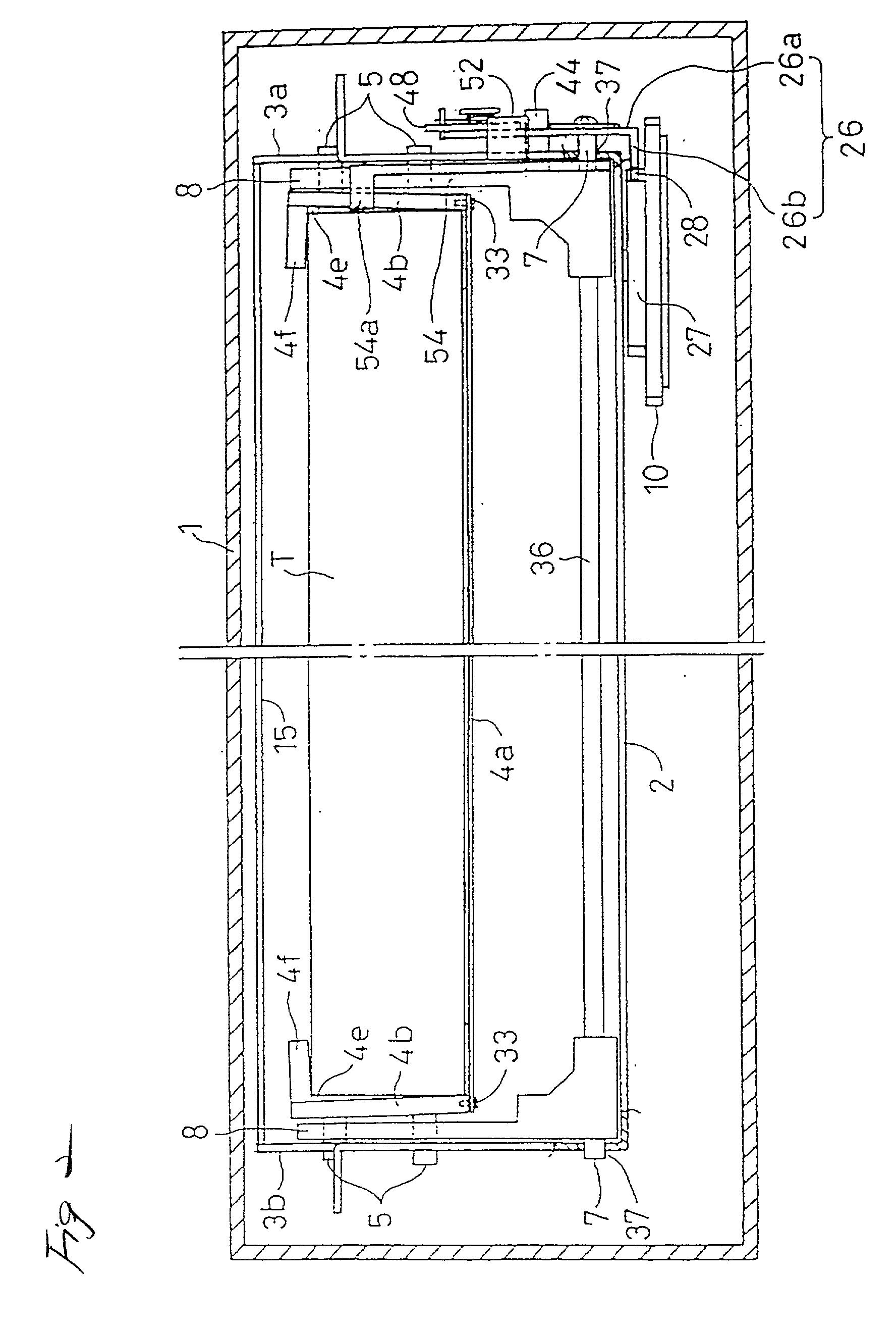
[0059] FIGS. 1 to 6 are diagrams showing a magnetic tape device according to one embodiment of the invention. A pair of side plates 4b, of a moving table 4, are secured to both ends of a bottom plate 4a using fixing tools 33, such as small screws, and a pair of integrally formed gripping members 4e are projected from the inner side faces of the side plates 4b. Further, a pair of float prevention projections 4f are integrally formed on the upper ends of the side plates 4b, and rotary levers 8 and a rotary cam 9 are coupled together, via a slide plate 26, and move forward and backward with the moving table 4, in directions a and b. For the other components, the same reference numerals are employed as are used for corresponding components in FIGS. 10 to 12, and no further explanation for them will be given.

[0060] As is shown in FIG. 7, the bottom plate 4a is a flexible steel plate, and a reinforcement projection 34 is formed inward, along the moving table 4 by bending the steel plate, ...


PUM


Abstract

A pair of float prevention members 4f are formed at the upper ends of side plates 4b of a moving table 4 to engage the upper edge of a tape cassette T. A pair of integrally formed gripping members 4e are projected inward at the corners between the float prevention members 4f and the side plates 4b, and are brought into contact with the side faces of the tape cassette T when it is inserted in to the moving table 4. A bottom plate 4a of the moving table 4 is flexible steel. When the bottom plate 4a is flexed by inserting the tape cassette T between the gripping members 4e, due to the urging force thus generated, the gripping members 4e are flexibly brought into contact with the side faces of the tape cassette T.

Description

[0001] 1. Technical Field[0002] The present invention relates to a magnetic tape device, having a simple and inexpensive structure, that can hold a tape cassette at a predetermined location on a moving table without unexpectedly wobbling.[0003] 2. Related Art[0004] An example conventional technique for a magnetic tape device, disclosed in the Unexamined Japanese Patent Application Publication No. Sho58-141461, will be described while referring to FIGS. 10 to 12. An upright pair of guide plates 3a and 3b are provided in parallel on a chassis 2 in a housing 1, and multiple guide pins 5 project from either side of a tape cassette moving table 4, located between the guide plates 3a and 3b. When these guide pins 5 are movably inserted into multiple L-shaped guide holes 6 that penetrate the guide plates 3a and 3b, the moving table 4 can move forward and backward, in directions a and b, between a cassette insertion position A and a cassette mounting position B. Then, rotary levers 8 are fi...

Claims


Application Information

Patent Timeline
IPC IPC(8): G11B15/675G11B25/06
CPCG11B15/67547G11B25/063
Inventor SAWAI, KUNIO
Owner FUNAI ELECTRIC CO LTD
Learn More