
Water purification device

Inactive Publication Date: 2002-07-18
JOHNSON ERIC SANFORD
View PDF8 Cites 7 Cited by
  • Summary
  • Abstract
  • Description
  • Claims
  • Application Information

AI Technical Summary

Benefits of technology

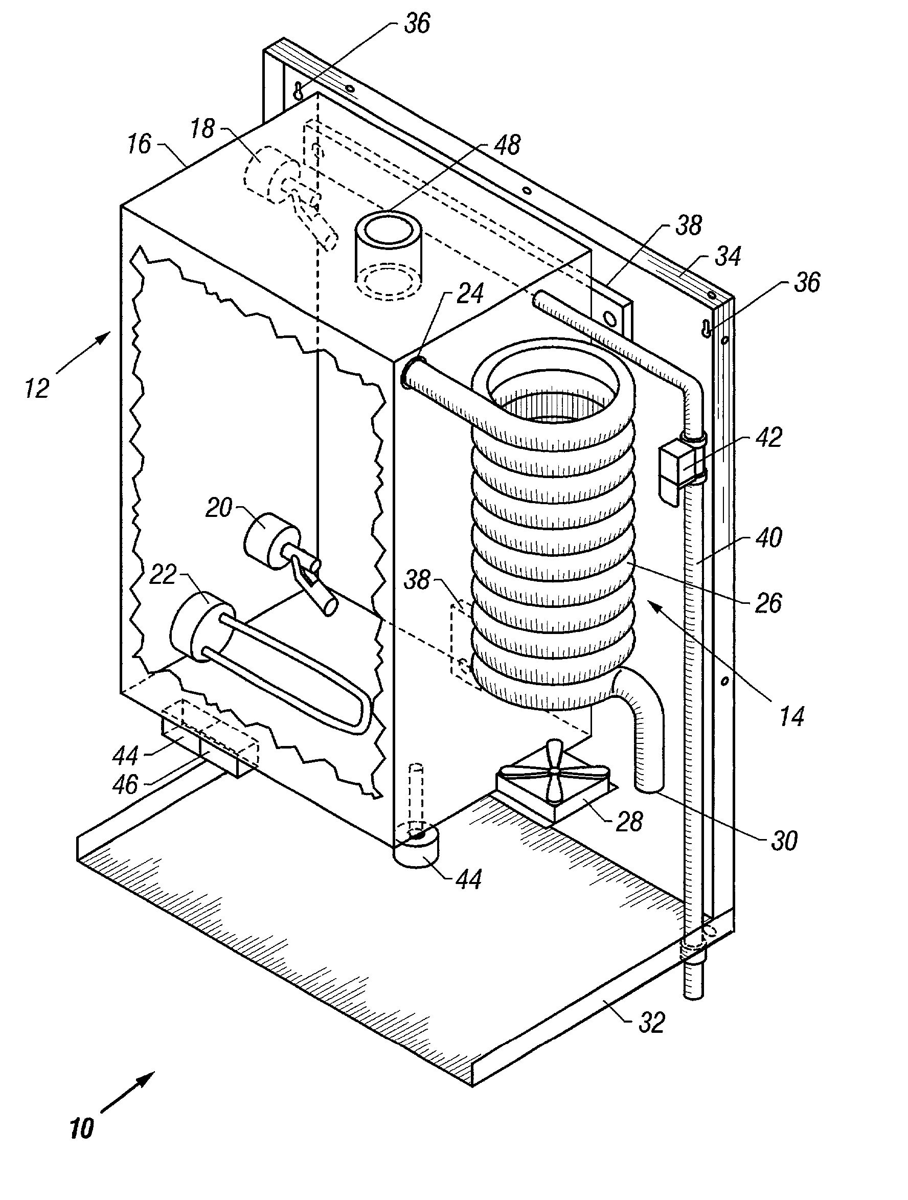
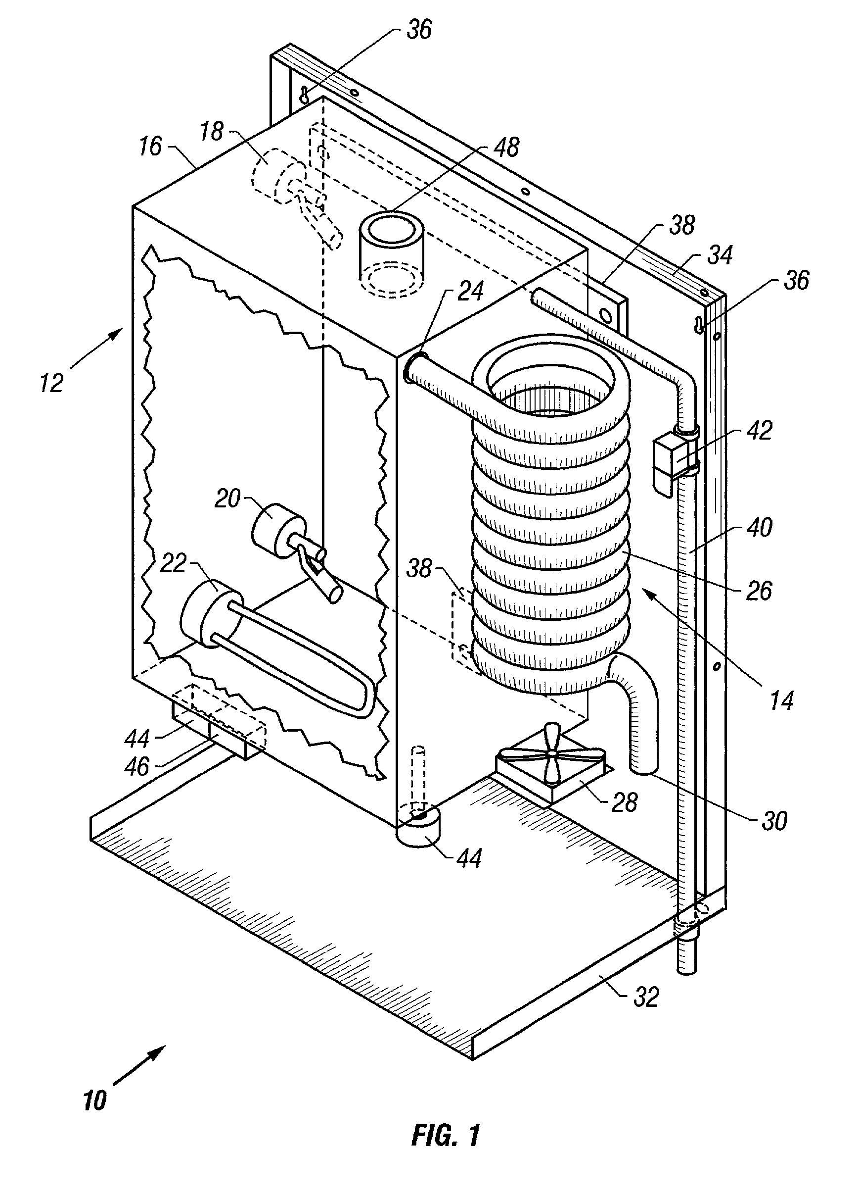
[0010] The still of this invention was specifically designed for simplicity of construction and operation, eliminating extraneous or unduly complex components. The still comprises a reservoir adapted to hold a quantity of water to be purified, such as for example 1-3 gallons of water. Float switches inside the reservoir include reed switches incorporated internally in the float body. The float switch provides control functions with an in-line, normally closed water supply valve and with an internal, always submerged heating element. In turn, these components are controlled by an electrical circuit comprising two electrical relays that enable water to be distilled through an air cooled condensing coil housed in a compact unitized body.

Problems solved by technology

One of the unfortunate results of the advancement of modem civilization to underdeveloped areas of the world is the increasing demand for pure drinking water.
Unfortunately, industrialization often places unprecedented demand on the water supply, while simultaneously spoiling much of the potable water which is available.
The systems described in these patents operate on a similar principal to the present invention, but are unnecessarily complex and therefore expensive.
In addition, the float switches and control components are of less efficient mechanical design and result in difficulty to configure a small and compact unit that is totally unitized and self contained.

Method used


Image

  • Water purification device
  • Water purification device
  • Water purification device

Examples


Embodiment Construction

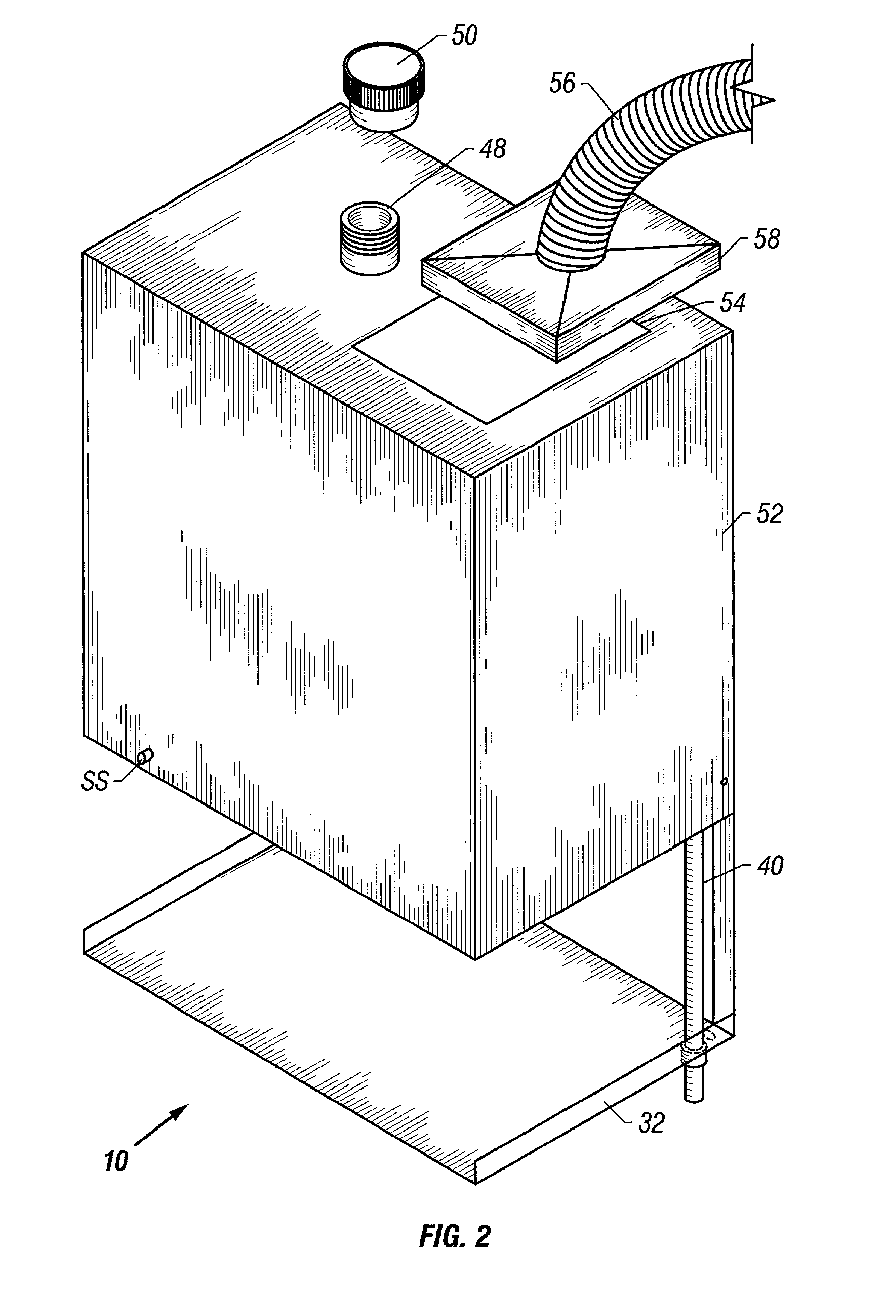
[0017] FIG. 1 depicts the preferred arrangement of the various components of the water purification device 10 of the present invention. The water purification device 10 comprises a distillation unit or boiler 12 on the left of FIG. 1 and a condensing unit 14 on the right side. This condensing chamber 14 contain the condensing coil 26 and the cooling fan 28. A feature of the present invention is that the components of the distilling apparatus 10 are unitized. As used in this specification, the term "unitized" refers to the feature that all the working components come as a unit, and for operation of the apparatus 10, all that remains in coupling the apparatus 10 to electrical power, and a source of water to be purified. The source of the water to be purified may be by hose coupling or manual fill, as described in further detail below.

[0018] The distillation unit 12 comprises a reservoir 16 to retain a quantity of water to be purified, and is preferably made of a durable material such ...


PUM

PropertyMeasurementUnit
Thicknessaaaaaaaaaa
Forceaaaaaaaaaa
Volumeaaaaaaaaaa

Abstract

A water purification device comprises a unitized self regulating water distillation unit for processing drinking water. The distillation system is simple, rugged, and inexpensive to install, operate, and maintain. Two internal float switches in combination with an in-line, normally closed water supply valve and with an internal and always submerged heating element that are controlled by an electrical circuit including two electrical relays that when effectively combined enable water to be distilled through an air-cooled condensing coil housed in a compact unitized body. A mechanical insulation barrier is also provided, insulating the exterior of the device from the heat of the distillation process as well as internally directing the heat generated by the distillation process so that may be exhausted. Water may therefore be processed easily and routinely on a daily basis with a minimal amount of effort, cost, and maintenance by the owner or owners of such a system.

Description

[0001] 1. Field of Invention[0002] The present invention relates to an apparatus for the purification of water by the distillation process for use as drinking water.[0003] 2. Description of Prior Art[0004] One of the unfortunate results of the advancement of modem civilization to underdeveloped areas of the world is the increasing demand for pure drinking water. Unfortunately, industrialization often places unprecedented demand on the water supply, while simultaneously spoiling much of the potable water which is available.[0005] Many solutions to the problem of purifying water for drinking have been proposed. Almost all solutions thus far advanced have been directed to large scale systems, in order to provide large quantities to large populations. While such systems are desperately needed, there also remains a need for small, inexpensive, simple to use systems for individual or family use.[0006] Among the solutions offered for the purification of water are filtration, chemical treat...

Claims


Application Information

Patent Timeline
IPC IPC(8): B01D1/00B01D3/42C02F1/04
CPCB01D1/0017B01D3/42C02F1/04
Inventor JOHNSON, ERIC SANFORD
Owner JOHNSON ERIC SANFORD
Learn More