Resin sealed semiconductor device
- Summary
- Abstract
- Description
- Claims
- Application Information
AI Technical Summary
Benefits of technology
Problems solved by technology
Method used
Image

Examples
first embodiment
[0028] [First Embodiment]
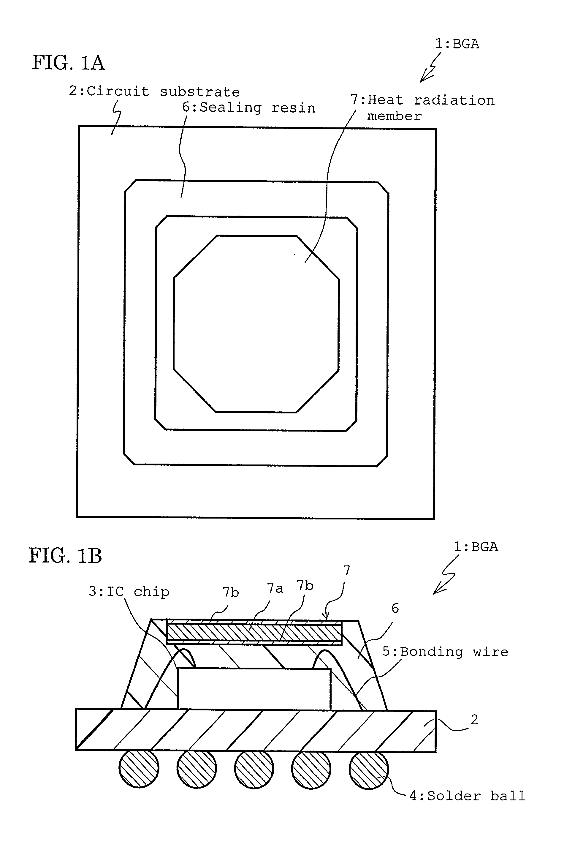
[0029] FIG. 1 shows a first embodiment of the present invention, FIG. 1A is a plan view of a resin sealed ball grid array (hereinafter abbreviated as BGA), and FIG. 1B is a sectional view thereof.
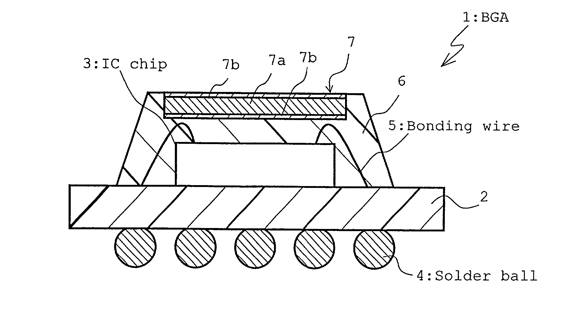
[0030] As shown in the drawings, a BGA 1 is a semiconductor device comprising a resin circuit substrate 2, an IC chip 3, and solder balls 4 as contact electrodes, and the IC chip 3 is mounted on an upper surface of the circuit substrate 2, and is connected to upper-surface electrodes (not shown) of the circuit substrate 2 via bonding wires 5.
[0031] The upper-surface electrodes are connected to a plurality of solder balls 4 disposed on an underside of the substrate via through hole electrodes (not shown) formed on the circuit substrate 2.
[0032] The IC chip 3 mounted on the circuit substrate 2 is resin-sealed by a sealing resin 6, and a metallic heat radiation member 7 is disposed above the IC chip 3. Then, the chip and the member are integrally fixed by the sealing r...
second embodiment
[0064] [Second Embodiment]
[0065] FIG. 3 shows a second embodiment of the present invention, FIG. 3A is a plan view of the BGA 1, and FIG. 3B is a sectional view thereof. In the drawings, a part similar to that of FIG. 1 is denoted with the same reference numeral and detailed description thereof is omitted.
[0066] In the present embodiment shown in FIG. 3, similarly as the first embodiment, a heat radiation member 17 is constituted of the clad material comprising the first metal 7a and the second metal 7b, and a protrusion 17a projecting on an IC chip 3 side is formed in a middle portion of the heat radiation member 17.
[0067] Since the protrusion 17a is formed on the heat radiation member 17, as shown in FIG. 3B, a distance between the IC chip 3 and the heat radiation member 17 can be reduced, the heat generated by the IC chip 3 can easily be conducted to the heat radiation member 17, and a heat radiation effect can further be enhanced.
[0068] Moreover, since the protrusion 17a project...
third embodiment
[0069] [Third Embodiment]
[0070] FIG. 4 shows a third embodiment of the present invention, FIG. 4A is a sectional view of the BGA 1, and FIG. 4B is a perspective view of the heat radiation member. Incidentally, also in the drawings, the part similar to that of FIG. 1 is denoted with the same reference numeral and the detailed description thereof is omitted.
[0071] In the embodiment shown in FIG. 4, a through hole 27a projecting in a funnel shape on the IC chip 3 side is formed in the middle portion of a heat radiation member 27 comprising the first metal 7a and the second metal 7b.
[0072] Since the through hole 27a is formed in the heat radiation member 27 in this manner, the resin can also be injected into the projecting through hole 27a during the injection molding of the sealing resin 6 (see FIG. 4A). Therefore, the distance from the IC chip 3 can be reduced, the heat radiation effect can be enhanced, and further an adhesive force between the heat radiation member 27 and the sealing...
PUM
 Abstract
Description
Claims
Application Information
 - R&D
- Intellectual Property
- Life Sciences
- Materials
- Tech Scout
- Unparalleled Data Quality
- Higher Quality Content
- 60% Fewer Hallucinations
Browse by: Latest US Patents, China's latest patents, Technical Efficacy Thesaurus, Application Domain, Technology Topic, Popular Technical Reports.
© 2025 PatSnap. All rights reserved.Legal|Privacy policy|Modern Slavery Act Transparency Statement|Sitemap|About US| Contact US: help@patsnap.com