Method and apparatus for displaying image by producing polarization inversion in ferroelectric member and producing contrast in contrast production member
- Summary
- Abstract
- Description
- Claims
- Application Information
AI Technical Summary
Benefits of technology
Problems solved by technology
Method used
Image
Examples
first embodiment
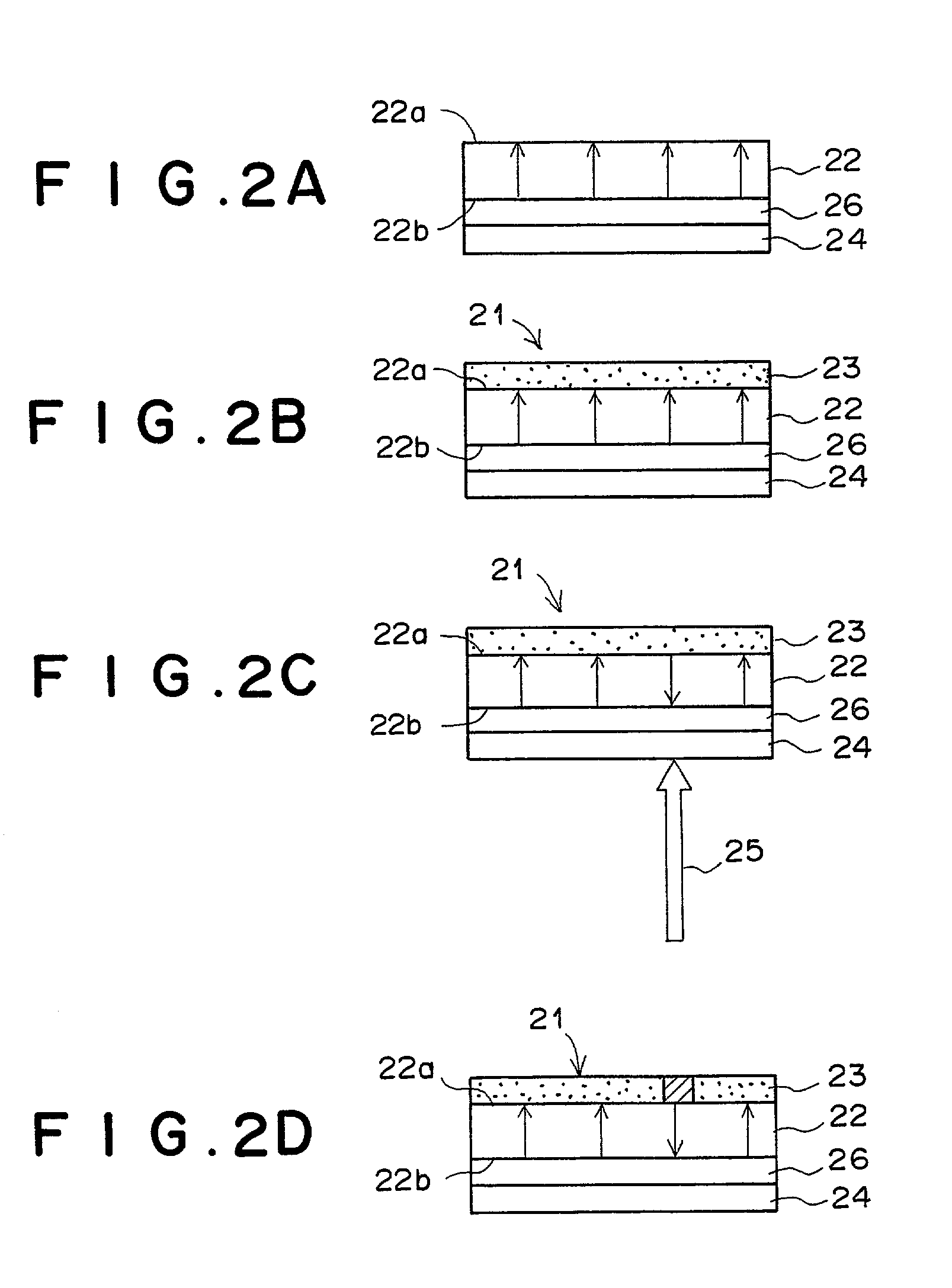
[0112] The first embodiment of the present invention is explained below with reference to FIGS. 2A to 2D. FIG. 2A shows a cross section of a portion of the image display medium in the first embodiment of the present invention, and FIGS. 2B to 2D show a cross section of the image display medium in the first embodiment of the present invention in three stages in a process for displaying an image according to the first aspect of the present invention. The image display medium in the first embodiment of the present invention is used for displaying a monochrome image.
[0113] In FIGS. 2A to 2D, reference numeral 21 denotes the image display medium, 22 denotes a Z-cut LiNbO.sub.3 substrate (hereinafter referred to as an LN substrate), 23 denotes a contrast production member, 24 denotes a transparent conductive film, 25 denotes infrared laser light, and 26 denotes a light-to-heat conversion film.
[0114] As illustrated in FIG. 2A, in order to produce the image display medium 21, the light-to-h...
second embodiment
[0126] The second embodiment of the present invention is explained below with reference to FIGS. 3A to 3D. FIG. 3A shows a cross section of a portion of the image display medium in the second embodiment of the present invention, and FIGS. 3B to 3D show a cross section of the image display medium in the second embodiment of the present invention in three stages in a process for displaying an image according to the first aspect of the present invention. The image display medium in the second embodiment of the present invention is also used for displaying a monochrome image. In FIGS. 3A to 3D, elements having the same reference numbers as FIGS. 2A to 2D have the same functions as the corresponding elements in FIGS. 2A to 2D, and only the differences from the first embodiment are explained below.
[0127] In FIGS. 3A to 3D, reference numeral 31 denotes the image display medium, 22 denotes a Z-cut LiNbO.sub.3 substrate (LN substrate), 32 denotes a contrast production member, 24 denotes a tr...
third embodiment
[0138] The third embodiment of the present invention is explained below with reference to FIG. 5, which is a diagram illustrating a cross section of a portion of the image display medium in the third embodiment of the present invention. In FIG. 5, the contrast production member 32 is not illustrated. The image display medium in the third embodiment of the present invention is also used for displaying a monochrome image. In FIG. 5, elements having the same reference numbers as FIG. 3A have the same functions as the corresponding elements in FIG. 3A, and only the differences from the second embodiment are explained below.
[0139] The image display medium in the third embodiment of the present invention is different from the image display medium in the second embodiment in that a light-to-heat conversion film 26 is provided instead of the periodical light-to-heat conversion film 36, and a periodically-transparent conductive film 34 is provided instead of the transparent conductive film 2...
PUM
 Abstract
Description
Claims
Application Information
 - R&D
- Intellectual Property
- Life Sciences
- Materials
- Tech Scout
- Unparalleled Data Quality
- Higher Quality Content
- 60% Fewer Hallucinations
Browse by: Latest US Patents, China's latest patents, Technical Efficacy Thesaurus, Application Domain, Technology Topic, Popular Technical Reports.
© 2025 PatSnap. All rights reserved.Legal|Privacy policy|Modern Slavery Act Transparency Statement|Sitemap|About US| Contact US: help@patsnap.com


