
System for digitally capturing and recording panoramic movies

a digital camera and film technology, applied in the field of very flexible digital cameras, can solve problems such as data loss or undesirable inter-frame artifacts, and achieve the effects of effective aperture, effective shutter speed, and easy and flexible control

Inactive Publication Date: 2002-04-18
GILBERT SCOTT +3
View PDF0 Cites 80 Cited by
  • Summary
  • Abstract
  • Description
  • Claims
  • Application Information

AI Technical Summary

Benefits of technology

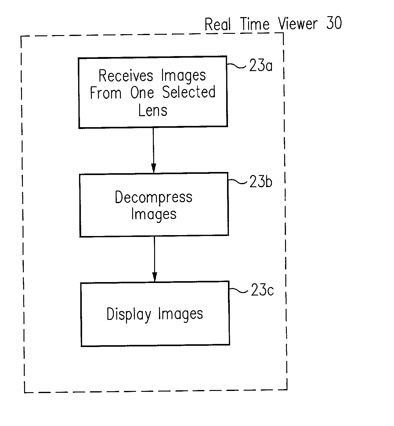
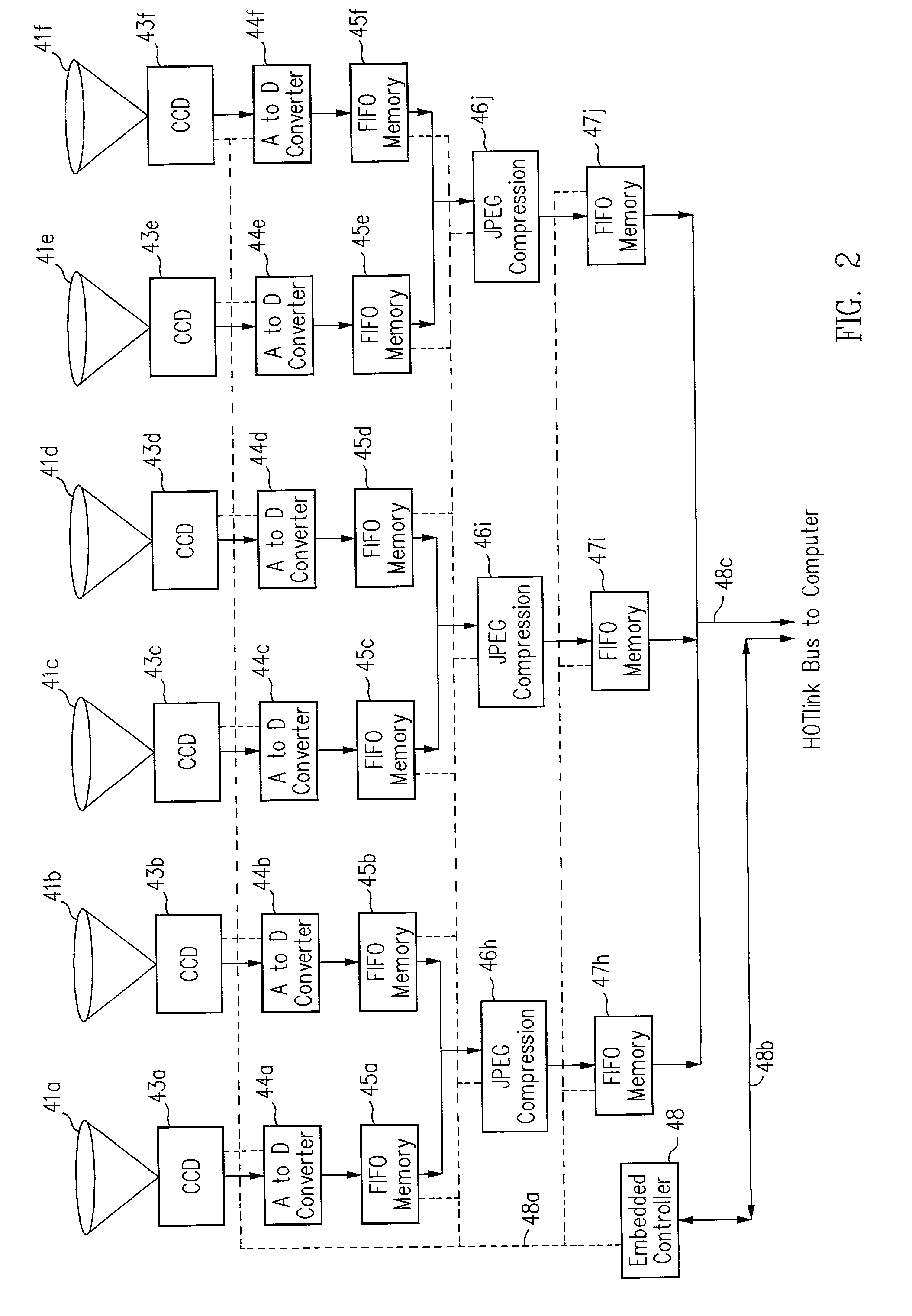
[0011] The present invention provides a very flexible, digital system for capturing and storing panoramic images using progressive scan (that is, non-interlaced) technology. The system includes a digital image input device and an associated control computer. Since the image capture device is digital it can be easily and flexibly controlled by software in the control computer. The image input device has six lenses positioned on the six faces of a cube. While the image input system can have other lens configurations, the use of six lenses in a cubic configuration is optimal for a system that is used to capture a spherical panorama. The six lenses simultaneously focus different images on six CCDs (Charge Coupled Devices). The image input device also includes an embedded controller, and data compression circuitry. The embedded controller controls the exposure time of the CCDs (i.e. the effective aperture and effective shutter speed) and reads image data from the CCDs. The image data read from the CCDs is compressed, multiplexed, and sent to the control computer. The control computer stores the images in frames, each of which have one image from each of the six lenses. Each frame includes six images that were simultaneously recorded and any associated information, such as audio tracks, textual information, or environmental information such as GPS (Global Position System) data or artificial horizon data. The control computer includes a user interface that allows a user to specify control information such as frame rate, compression ratio, gain, etc. The control computer sends control information to the embedded controller which in turn controls the CCDs and the compression circuitry. The images can be sent from the control computer to a real time viewer so that a user can determine if the correct images are being captured. The images stored at the control computer are later seamed into panoramas and made into panoramic movies.

Problems solved by technology

However, irrespective of how the interlacing is eliminated, data is lost or undesirable inter-frame artifacts are introduced into 22 the resulting non-interlaced images.

Method used


Image

  • System for digitally capturing and recording panoramic movies
  • System for digitally capturing and recording panoramic movies
  • System for digitally capturing and recording panoramic movies

Examples


Embodiment Construction

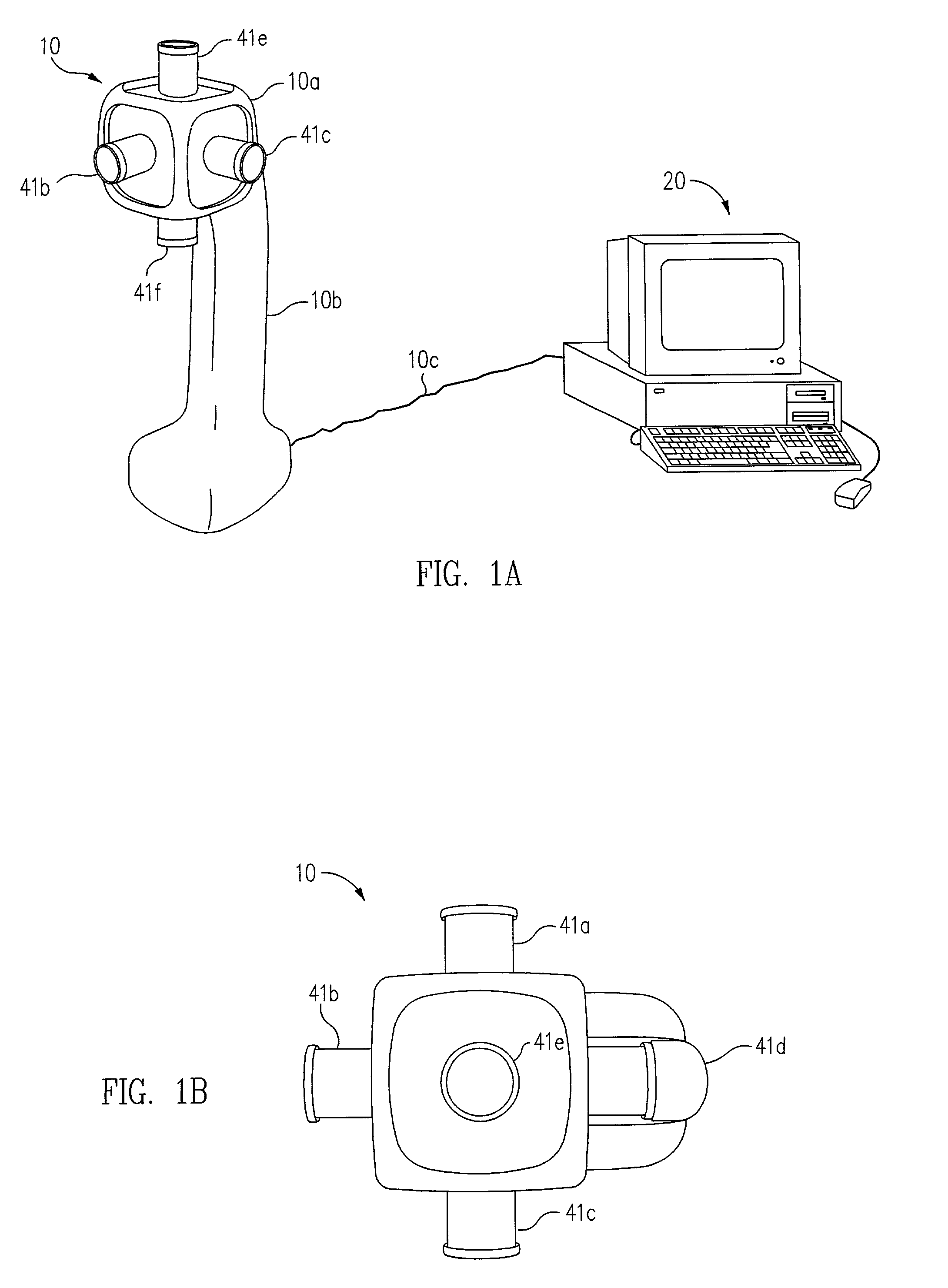
[0031] An overall diagram of a preferred embodiment of the invention is shown in FIG. 1. There is a digital image capture device 10 that is connected to a control computer 20 by a cable 10c. Image capture device 10 has six lenses 41a to 41f positioned on the six sides of a cube shaped frame 10a. FIG. 1B is a top view of image capture device 10 which shows some of the lenses 41a to 41f that are not visible in FIG. 1A. The cube 10a is mounted on top of a handle 10b.

[0032] A block diagram of the electronic components inside of image capture device 10 is shown in FIG. 2. There are six CCD devices 43a to 43f, one associated with each of the lenses 41a to 41f. Each lens 41 projects an image onto the associated CCD device 43. Each lens 41 has a 135 degree filed of view. Thus, the various images have some overlap to insure that the images can be seamed into a complete panorama without any missing areas. The field of view of the lenses is chosen to provide enough overlap for efficient seamin...


PUM


Abstract

The present invention provides a very flexible, digital system for capturing and storing panoramic images using progressive scan (that is, non interlaced) technology. The system includes a digital image input device and an associated control computer. Since the image capture device is digital it can be easily and flexibly controlled by software in the control computer. The image input device has six lenses positioned on the six faces of a cube. While the image input system can have other lens configurations, the use of six lenses in a cubic configuration is optimal for a system that is used to capture a spherical panorama. The six lenses simultaneously focuses different images on six CCDs (Charge Coupled Devices). The image input device also includes an embedded controller, and data compression circuitry. The embedded controller controls the exposure time of the CCDs (i.e. the effective aperture and effective shutter speed) and reads image data from the CCDs. The image data read from the CCDs is compressed, multiplexed, and sent to the control computer. The control computer stores the images in frames, each of which have one image from each of the six lenses. Each frame includes six images that were simultaneously recorded and any associated information, such as audio tracks, textual information, or environmental information such as GPS (Global Position System) data or artificial horizon data. The control computer includes a user interface which allows a user to specify control information such as frame rate, compression ratio, gain, etc. The control computer sends control information to the embedded controller which in turn controls the CCDs and the compression circuitry. The images can be sent from the control computer to a real time viewer so that a user can determine if the correct images are being captured. The images stored at the control computer are later seamed into panoramas and made into panoramic movies.

Description

[0001] The present invention is a continuation of application Ser. No. 09 / 338,790 which was filed May 23, 1999, a continuation in part of application Ser. No. 09 / 310,715 which was filed May 12, 1999, and which is a continuation in part of application 60 / 085,319 which was filed May 13, 1998. The content of the above listed applications are hereby incorporated herein by reference in their entirety.[0002] The present invention relates to photography and more particularly to a system for digitally capturing and recording panoramic images.COPYRIGHT NOTICE[0003] A portion of the disclosure of this patent document contains material which is subject to copyright protection. The copyright owner has no objection to the facsimile reproduction by anyone of the patent document or the patent disclosure, as it appears in the Patent and Trademark Office patent file or records, but otherwise reserves all copyright rights whatsoever.[0004] A panoramic image is an image with a wide field of view. A pa...

Claims


Application Information

Patent Timeline
IPC IPC(8): H04N5/232H04N5/77H04N7/18H04N9/804H04N9/806H04N9/82
CPCH04N5/232H04N5/23238H04N5/77H04N7/181H04N9/8233H04N9/806H04N9/8211H04N9/8227H04N9/8047H04N23/50H04N23/661H04N23/698H04N23/632
Inventor GILBERT, SCOTTKAIMAN, DAVID J.PARK, MICHAEL C.RIPLEY, G. DAVID
Owner GILBERT SCOTT
Learn More