
Multi-circular flux motor

a flux motor and multi-circular technology, applied in the direction of magnetic circuits, electrical apparatus, dynamo-electric machines, etc., can solve the problems of difficult configuration of the motor structure, limitation of design, and difficult application of the switched reluctance motor structure in the ac machin

Inactive Publication Date: 2002-03-14
ENERGY DEVICES
View PDF7 Cites 12 Cited by
  • Summary
  • Abstract
  • Description
  • Claims
  • Application Information

AI Technical Summary

Problems solved by technology

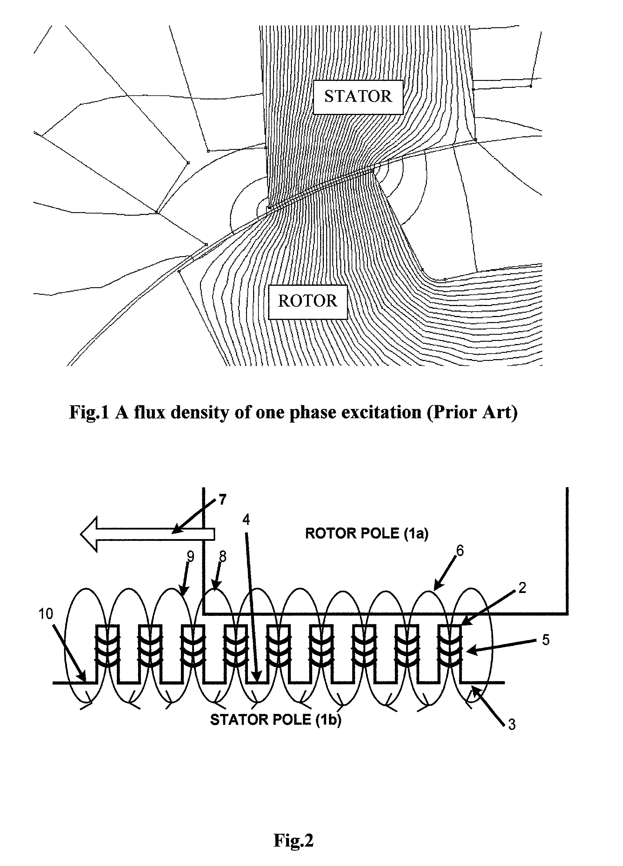
However, the short flux loop machine such as a 12 / 10 pole switched reluctance motor (see invention U.S. Pat. No. 4,883,999) has limitation of designs.
Switched reluctance motor structures are difficult to apply in an AC machine unlike synchronous reluctance motors that can apply in AC machine except just they have a complex rotor which difficult to build.
Conventional switched reluctance motors are usually work by a long flux loop with a fully aligned and fully unaligned condition of their big tooth makes very hard to configure the motor structure.
For example, the 12 / 10 poles 3-phase (see invention U.S. Pat. No. 4,883,999) and a characteristic of the motor type are a highly non-linear, therefore the potential of high-speed application is limited by core loss, switching loss and low inductance ratio making a low torque output and very difficult to control by the problem of a non-linear characteristic of the motor.
The disadvantage of the series connection is using a high voltage source.
The parallel connection, an inductance and a flux-linkage profile also are increasing by linear but it has a low scale changing make difficult of finding rotor position.

Method used


Image

  • Multi-circular flux motor
  • Multi-circular flux motor
  • Multi-circular flux motor

Examples


Embodiment Construction

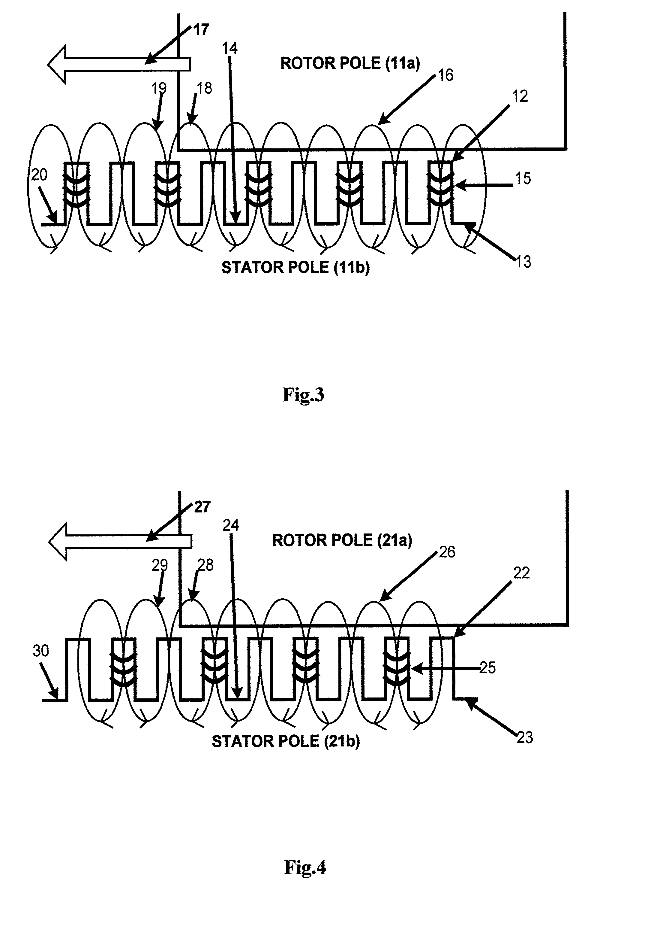
[0031] From the simple invention, it can apply in several types of invention such as the linear motor or actuator in FIG. 10. The invention comprised with the stator part (40), the rotor part (41), the windings (42) and rotor support (43). The windings generate multi-circular flux loops (44) and the most effective circular flux loop (46) produces reluctance torque make the rotor or actuator move to direction (45).

[0032] To control the movement direction of the invention, at lest has to be a 3-phase machine. The simple invention shown in FIG. 10 can be configured to a 3-phase linear motor as shown in FIG. 11a and FIG. 11b. The linear motor shown in FIG. 11a, having an overlapping and interaction between phases through the rotor body (48) by ratio of 1 / 3 of the rotor width in the 3-phase machine. For different configuration such as a 4-phase, 5-phase and 6-phase an overlapping are 1 / 4, 1 / 5 and 1 / 6, respectively. The linear motor can use with DC pulse and AC source in the same structur...


PUM


Abstract

An invention is a new type of motor, a multi-circular flux motor. The invention has simple structure and comprises of a salient pole rotor and the silent pole stator. The stator pole is subdivided into plural teeth with the individual winding. A group of windings of each stator pole is connected in either series or parallel and is driven by one excitation phase. The movement of the invention uses multi-circular flux loops to produce reluctance torque to make the rotor moves. The multi-circular flux loops comprise of a series of flux loops that every flux loop is inversely rotation direction to each other adjacent. The invention can apply in a linear and rotating machine. By having plural winding poles and phases, the invention can be a poly-phase machine. The invention can be designed to be any number of poles and phases because all flux loops are separated. The invention is applied in both AC and DC machine and both linear and rotating machine. The rotor core can be replaced with a lightweight material or hollowed out to be a lightweight rotor. The invention can be designed to be a toothless-stator or toothless-rotor machine.

Description

[0001] The invention related to a reluctance motor with a silent pole rotor and stator having winding on either a rotor pole or a stator pole. The invention is a new type of machine in its class because it uses the new technique, multi-circular flux loops (a series of flux loop or a series of circular flux loops), to produce reluctance torque. The invention can implement in alternating current (AC) and direct current (DC) pulse. The invention can apply with a simultaneous phase excitation without flux cancellation between phases. The invention has no a permanent magnet on both a rotor pole and a stator pole, has a simple salient pole and has no physical commutation but commutates by means of electronically commutation.BACKGROUNG OF INVENTION[0002] The invention is built up by using the principle of reluctance torque. This invention can be named `a multi-circular flux motor` the background of the technique came from a short flux loop of a reluctance machine especially a switched relu...

Claims


Application Information

Patent Timeline
Patent Type & Authority Applications(United States)
IPC IPC(8): H02K19/10
CPCH02K19/103
Inventor JINUPUN, PORAMASTE
Owner ENERGY DEVICES
Learn More