Tool for chip removing machining and having fluid-conducting branch ducts
- Summary
- Abstract
- Description
- Claims
- Application Information
AI Technical Summary
Benefits of technology
Problems solved by technology
Method used
Image
Examples
Embodiment Construction
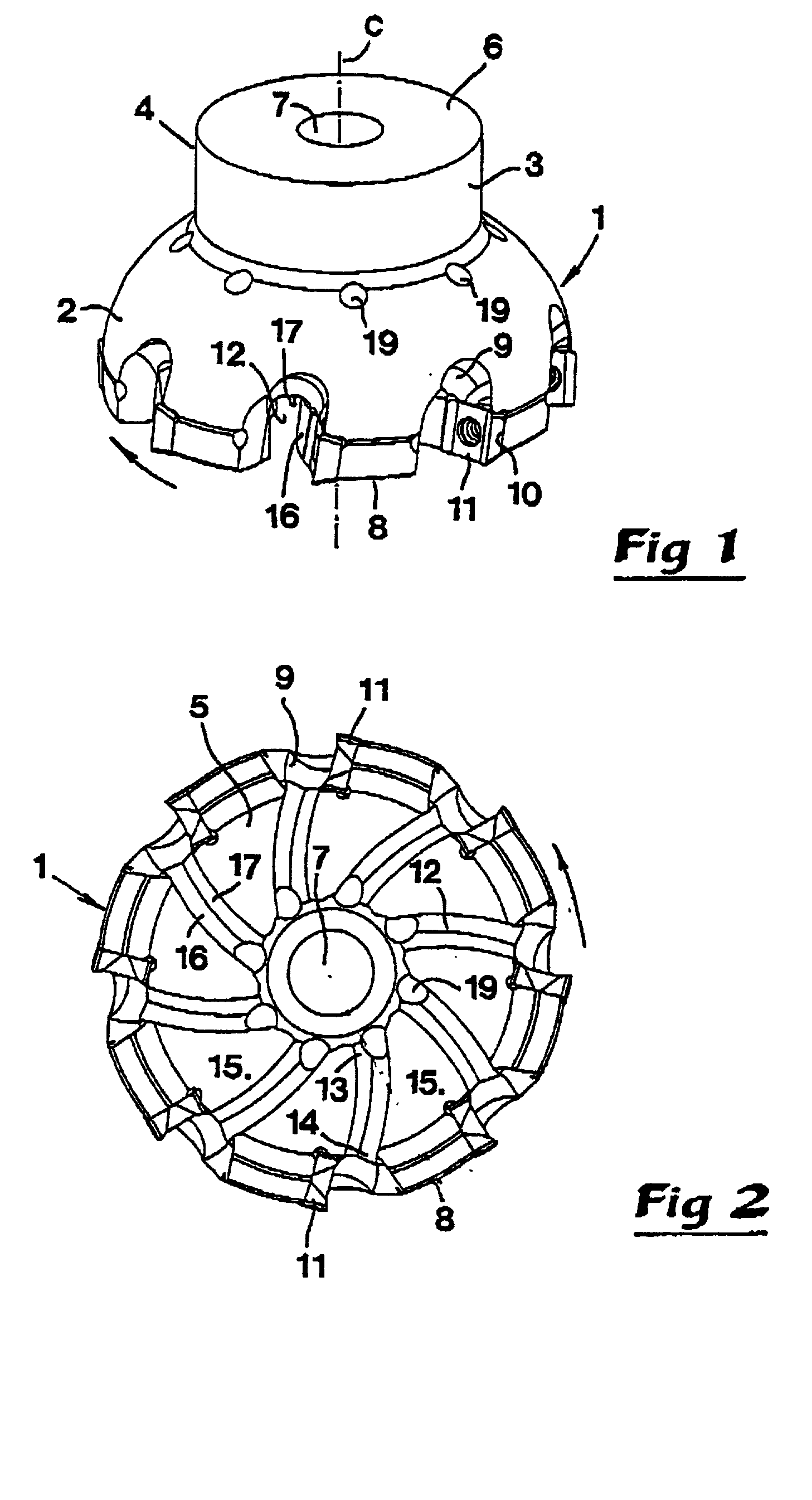
[0027] The tool illustrated in FIGS. 1 and 2 is in the form of a cutter head 1 which is rotatable around a central, geometrical axis of rotation C. A convexly spherical envelope surface 2 extends rotationally symmetrically around the axis C, which surface 2 transforms into a cylinder surface 3 on a shaft-like portion 4 of the cutter head. A first, planar end surface 5 which is opposite a second planar end surface 6 on the shaft portion 4 extends perpendicularly to the axis of rotation C. Between these end surfaces 5, 6, a central main duct 7 extends, in the form of a hole, e.g. a bore hole, through which cooling liquid or another fluid may pass. In an edge portion 8 forming a transition between the envelope surface 2 and the end surface 5, a plurality of tangentially spaced recessed chip spaces 9 are formed. In connection with said chip spaces, seats 10 are formed in which cutting inserts 11 are removably mounted. It is to advantage if said cutting inserts are of an indexable type, ...
PUM
 Abstract
Description
Claims
Application Information
 - R&D
- Intellectual Property
- Life Sciences
- Materials
- Tech Scout
- Unparalleled Data Quality
- Higher Quality Content
- 60% Fewer Hallucinations
Browse by: Latest US Patents, China's latest patents, Technical Efficacy Thesaurus, Application Domain, Technology Topic, Popular Technical Reports.
© 2025 PatSnap. All rights reserved.Legal|Privacy policy|Modern Slavery Act Transparency Statement|Sitemap|About US| Contact US: help@patsnap.com


