
Self-fixing bolt and an assembly thereof attached to a panel

a self-fixing bolt and assembly technology, which is applied in the direction of threaded fasteners, screwdrivers, manufacturing tools, etc., can solve the problems of affecting the mechanical strength of the embossed region, unable to meet such a requirement, and unable to be disposed in a narrow space restricted by the design structure of cars

Inactive Publication Date: 2001-12-06
SHINJO MFG CO LTD
View PDF0 Cites 8 Cited by
  • Summary
  • Abstract
  • Description
  • Claims
  • Application Information

AI Technical Summary

Benefits of technology

[0009] Also preferably, those lugs may gradually decrease their size or width in a tangential direction and towards the end opening so as to terminate at a middle height of the outer periphery. Such a bolt will show a diminished resistance to the punching thrust applied thereto, nevertheless enhancing its anti-rotation effect.

Problems solved by technology

Therefore, those excessively large flanges formed each between the threaded body and the barrel portion have made it difficult to meet such a requirement.
Each of self-fixing bolts of this type does need a relatively wide area for attachment thereof, sometimes making it impossible to be disposed in a narrow space restricted due to the designed structure of cars.
Such an embossing for bringing the flange's upper surface in flush with the panel surface does however impair mechanical strength of the embossed region, particularly against a driving thrust that will occasionally be imparted to the threaded body during use.

Method used


Image

  • Self-fixing bolt and an assembly thereof attached to a panel
  • Self-fixing bolt and an assembly thereof attached to a panel
  • Self-fixing bolt and an assembly thereof attached to a panel

Examples


Embodiment Construction

[0021] Now some embodiments of the present invention will be described in detail referring to the drawings.

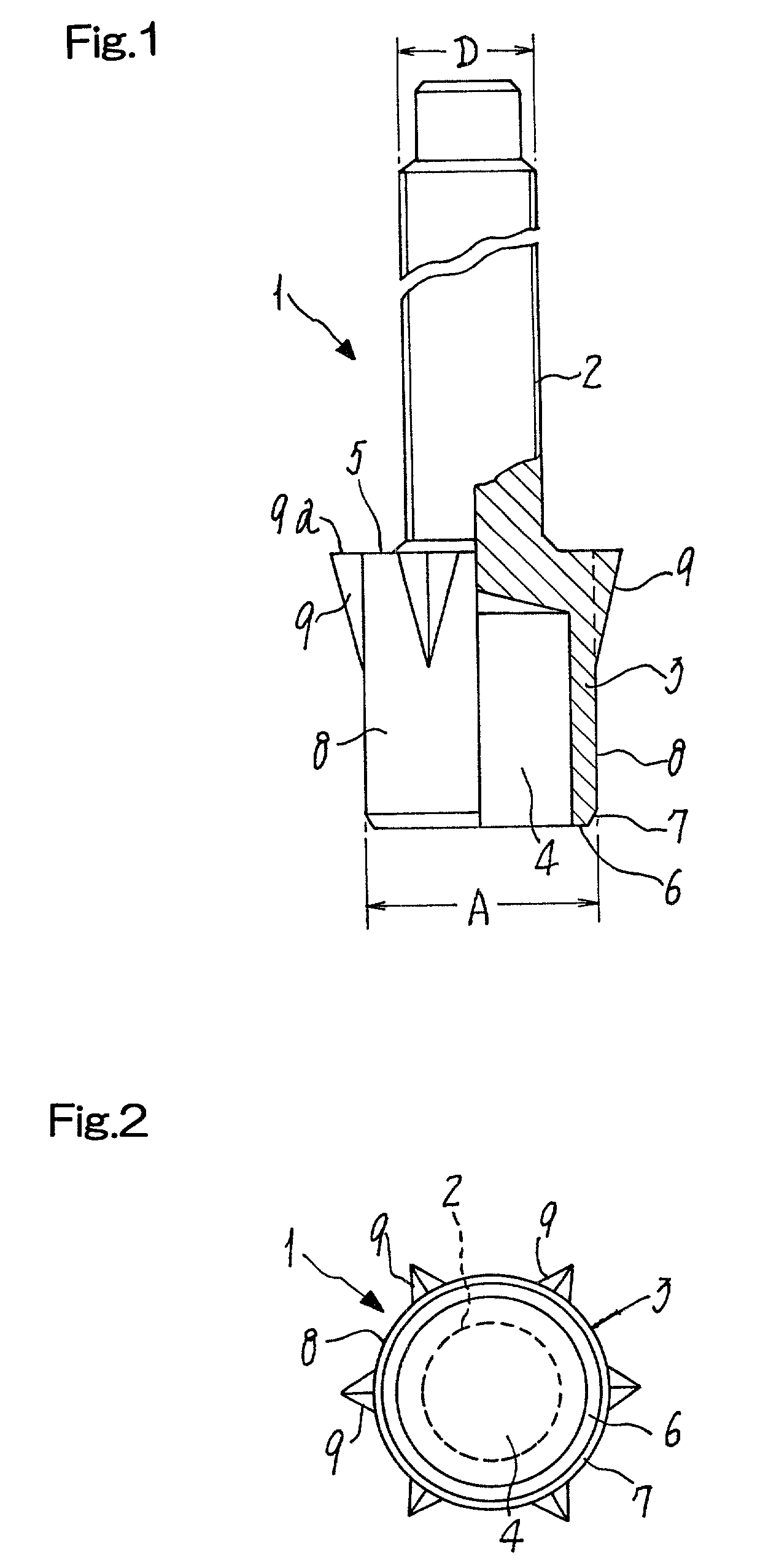
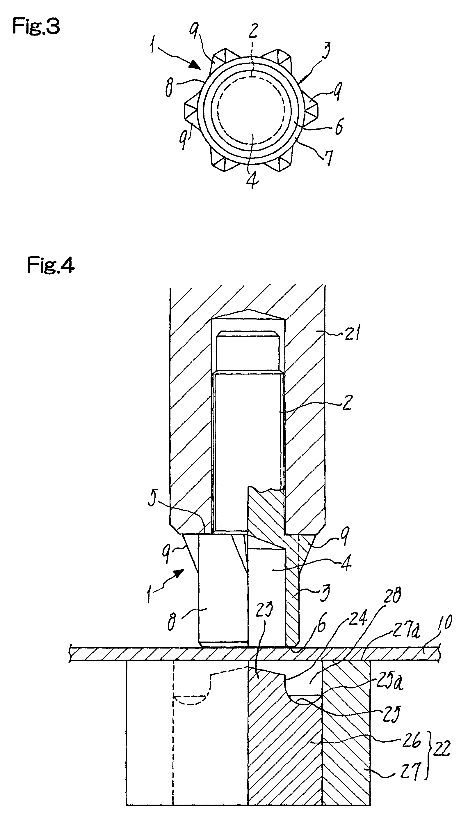
[0022] FIGS. 1 and 2 show a self-fixing bolt 1 provided herein. The bolt 1 comprises a male-threaded body 2 whose lower end is integral with an annular barrel portion 3. This portion 3 serving as a member for punching a hole in a metal panel and having an end opening or cavity 4 extends coaxially with the threaded body 2. The diameter `A` of the barrel portion 3 is somewhat greater than the diameter `D` of the threaded body 2, so that an annular thrust-bearing shoulder is formed at the upper end of said barrel portion. The lower end of the barrel portion 3 are formed as an annular punching face 6 and a beveled guide 7 extending obliquely and upwards from the punching face. The barrel portion 3 has an outer periphery 8 from which a plurality of (`6` in the illustrated example) anti-rotation lugs 9 such that they are pointed outwardly in radial direction and do extend longitudina...


PUM


Abstract

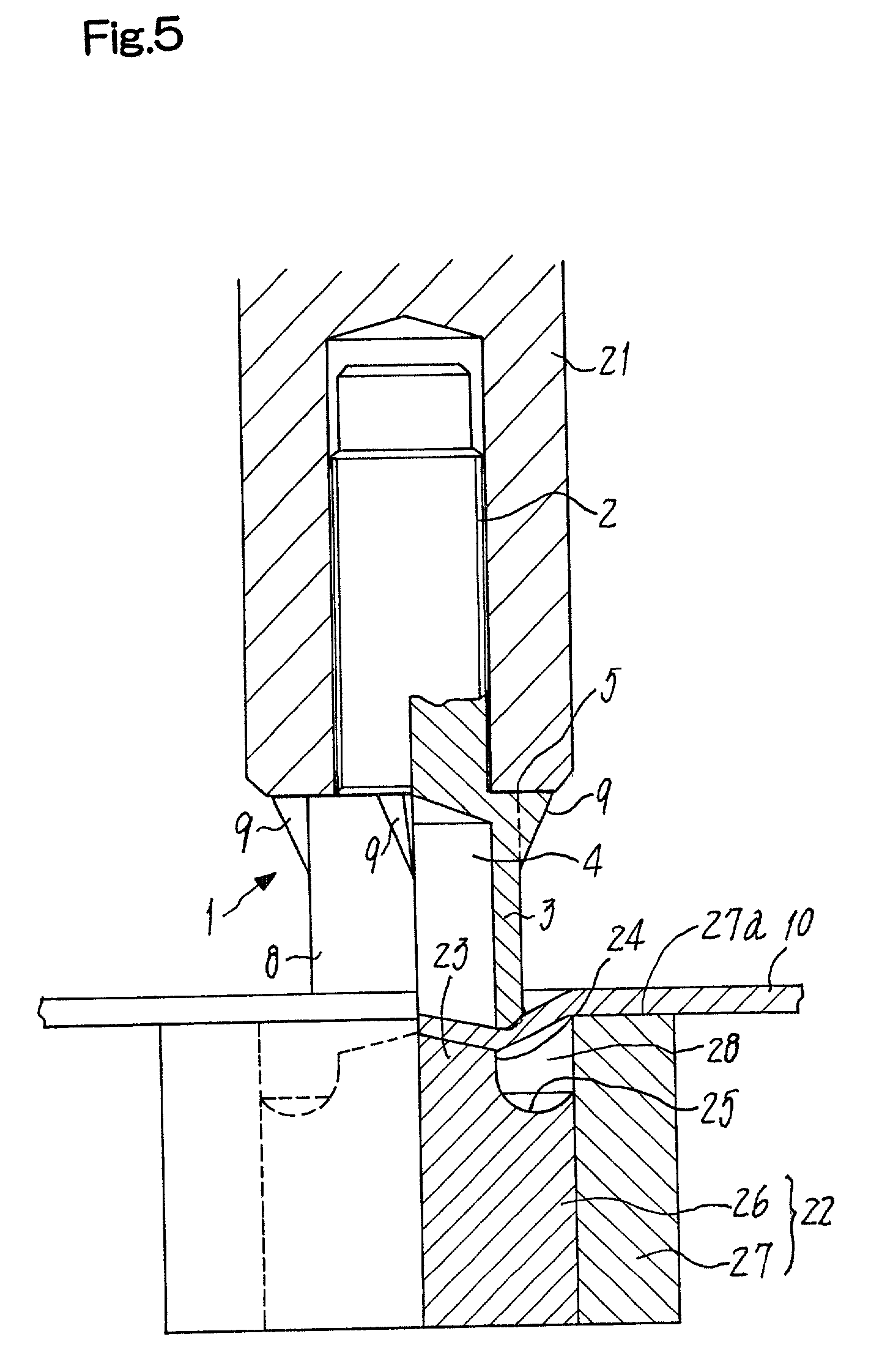
A self-fixing bolt 1 has a male-threaded body 2 and an annular barrel portion 3 having an upper region that continues from the lower end of the body. The barrel portion 3 has an outer periphery larger in diameter than the body 2, the barrel portion having a cylindrical opening 4 with a lower end to punch a hole in the metal panel 10 when driven to be attached to this panel. The bolt has a thrust-bearing shoulder 5 formed integral with the upper region of the barrel portion. Anti-rotation retentive lugs 9 protrude in a longitudinal direction from the outer periphery 8 of the barrel portion to be pointed outwards in a radial direction, each lug 9 being of a triangular or trapezoid cross section, so that the bolt is not accompanied by any oversized flange, thus rendered smaller in size and lighter in weight, and nevertheless surely protected from any undesired idle rotation relative to the panel when the its portion and the bolt form an assembly.

Description

[0001] The present invention relates to a self-fixing bolt for punching a metal panel to form an opening that will permanently secure the bolt therein due to a riveting effect. The present invention also relates to an assembly of such a panel portion and a self-fixing bolt riveted thereto.PRIOR ART[0002] Some types of the self-fixing bolts and the assemblies thereof each riveted to a metal panel are known as disclosed for example in the Japanese Utility Model Laying-Open Gazette Sho.58-135516 and the Patent Publication Hei.7-41357.[0003] Those self-fixing bolts have each a male-threaded body and an annular barrel portion continuing therefrom. The lower end or rim of such a portion will be deformed outwardly in radial direction when striking it into the metal panel to firmly attach the bolt to an opening thus punched in said panel.[0004] The prior art self-fixing bolts generally have large flanges disposed at the upper ends of their barrel portions. Those flanges are of a diameter ex...

Claims


Application Information

Patent Timeline
Patent Type & Authority Applications(United States)
IPC IPC(8): F16B35/04B23P19/06F16B37/06
CPCB23P19/062F16B37/065F16B37/068
Inventor SHINJO, KATSUMI
Owner SHINJO MFG CO LTD
Learn More