
Mooring systems with active force reacting systems and passive damping

a technology of active force and reacting system, applied in vessel construction, special-purpose vessels, transportation and packaging, etc., can solve the problems of increasing damping, increasing the damping of spring-like systems, and insufficient damping of vessels moving through water

Inactive Publication Date: 2001-10-18
SOFEC
View PDF0 Cites 59 Cited by
  • Summary
  • Abstract
  • Description
  • Claims
  • Application Information

AI Technical Summary

Benefits of technology

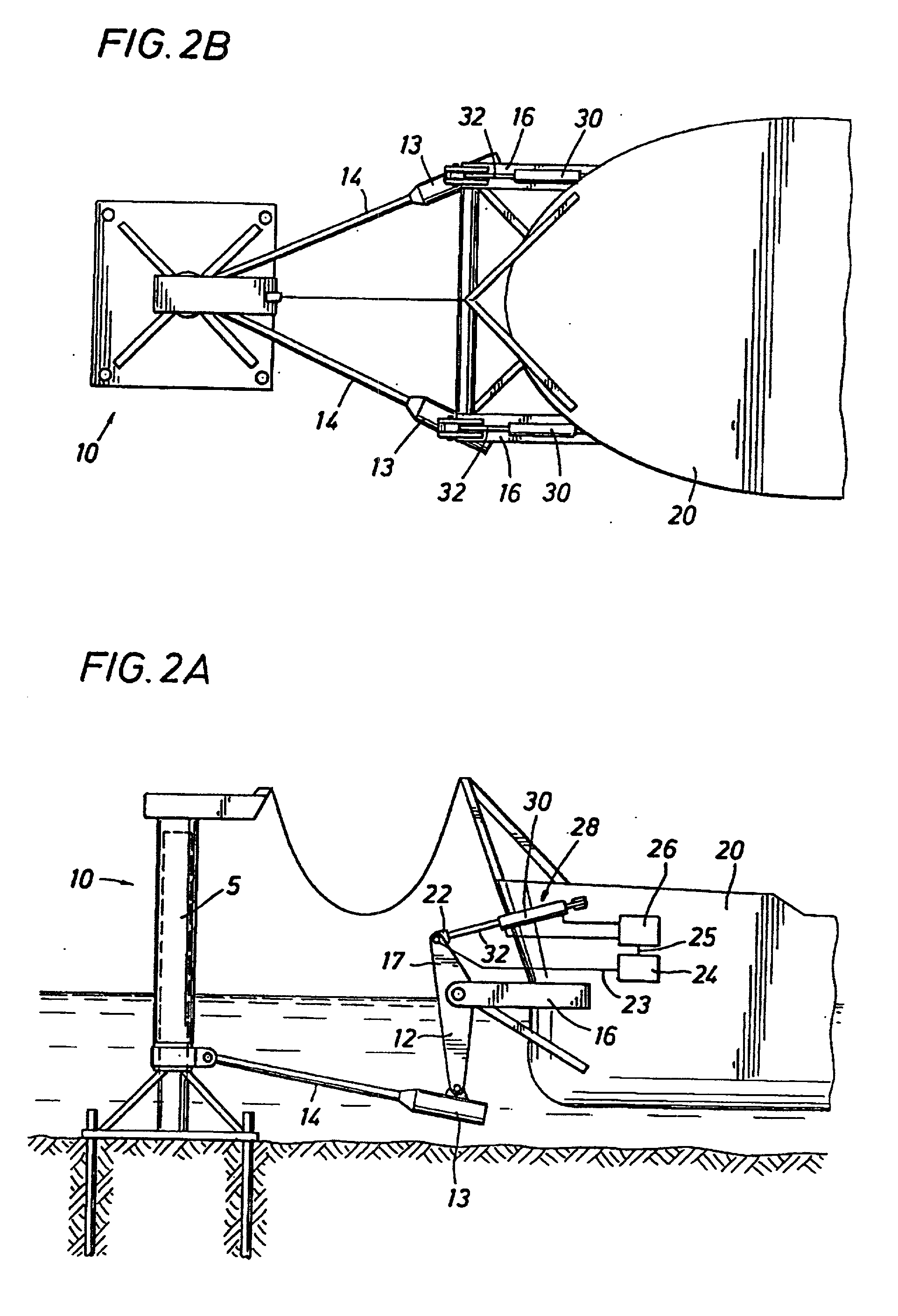
[0014] A primary object of the invention is to provide an active "forcing system" or active damping system by which excursions of a vessel past a neutral point of a yoke of a stationary body-yoke-vessel system are opposed by an active controlled restoring force. By applying such controlled force, displacement amplitudes of the vessel can be reduced or even eliminated, with the result that the overall size, weight and cost of the mooring system can be reduced.

Problems solved by technology

The movement of the cables in the water increases damping of the spring effect of the weighted yoke arms.
A weight at the end of the yoke suspended from cables or rods from the vessel causes the yoke to act like a pendulum or undamped spring, but the water acting on the suspension members and yoke damps the spring-like system more than if the yoke were entirely above water.
The momentum of the vessel causes it to move through the neutral point of the yoke and to move to the other side of it due to the system's inherent lack of energy dissipation, and because the counter restoring force of the system cannot be generated until the vessel passes through the neutral or quiescent point to the other side.
The natural damping force of the vessel moving through the water is not enough to prevent oscillatory motion of the vessel.

Method used


Image

  • Mooring systems with active force reacting systems and passive damping
  • Mooring systems with active force reacting systems and passive damping
  • Mooring systems with active force reacting systems and passive damping

Examples


Embodiment Construction

[0045] Soft yoke mooring systems rely on restoring forces generated by linkages connected to pendular weights. As a result, the restoring force is sinusoidal with displacement as shown in curve "A" of FIG. 1. FIG. 1 is a restoring force versus displacement diagram showing restoring force as a function of displacement of a yoke from a vessel. The neutral or quiescent point is the position of the yoke when the vessel is at rest. Because the restoring force for displacements about the neutral point is so low (essentially zero), soft yoke systems i.e. pendular yoke systems as illustrated by curve A require relatively large displacements to generate the required restoring force and absorb kinetic energy. This characteristic requires large linkages and weights which implies high cost of steel structures. Because there is little damping, peak compression loads toward the tower of a magnitude of 5 / 9 of peak tension loads away from the tower are seen. For example, the compression restoring f...


PUM


Abstract

A mooring system including a body / arm / vessel arrangement with passive damping and / or an active force restoring system. The active force restoring system includes a sensor for generating a displacement signal representative of the displacement of the vessel from a quiescent position and an active forcing device which responds to the displacement signal to force the arm in a direction to move the vessel toward the quiescent position. The passive damping arrangement includes a device, independent of and in addition to the damping of the water on the vessel or the arm, that damps the oscillation of the vessel in response to environmental conditions which force the vessel from its quiescent position. Hydraulic cylinder arrangements are provided for active forcing and passive damping. Powered winch / cable arrangements are also provided for active force systems. Alternative devices for active and passive damping systems of torque actuators include hydraulic powered cans with internal fins, or cans with internal elastomeric elements or disk brake elements.

Description

[0001] This Non-Provisional Application claims priority from Provisional Application 60 / 175,150 filed on Jan. 7, 2000.[0002] 1. Field of the Invention[0003] This invention relates generally to the field of mooring arrangements for vessels, particularly offshore vessels such as Floating Production and Offloading Vessels (FPSOs) or Floating Storage and Offloading vessels (FSOs) used in offshore hydrocarbon production. Still more particularly, the invention concerns active and passive damping arrangements for yoke / spring systems and yoke / pendulum systems which are spring-like to restore a vessel toward an equilibrium position with respect to a generally stationary body such as a tower or an anchored buoy.[0004] 2. Description of the Prior Art[0005] There are numerous examples of yoke arrangements that couple a vessel to a body such as a tower or an anchored buoy or other generally stationary body. U.S. Pat. No. 4,290,158 shows a mooring yoke for a vessel which is coupled for rotation w...

Claims


Application Information

Patent Timeline
Patent Type & Authority Applications(United States)
IPC IPC(8): B63B21/00B63B21/50B63B22/02
CPCB63B21/00B63B21/50B63B22/02B63B2021/001B63B2021/008
Inventor COTTRELL, ROY H.BOATMAN, L. TERRYLIU, YONGHUI
Owner SOFEC
Learn More