
Method and apparatus for photon therapy

a technology of photon therapy and photon beam, applied in the field of photon beam therapy, can solve the problems of inability to guarantee the priority of successive treatments, inability to provide a complete range of flexibility in choosing treatment parameters, and inability to guarantee the consistency of treatment priorities

Inactive Publication Date: 2001-07-19
VAN ZUYLEN JEFFREY +2
View PDF0 Cites 68 Cited by
  • Summary
  • Abstract
  • Description
  • Claims
  • Application Information

AI Technical Summary

Benefits of technology

The system enables complete, accurate, and consistent characterization of treatments, providing a high degree of flexibility and safety features, such as real-time luminous output feedback and built-in diagnostics, to optimize treatment outcomes and prevent ocular hazards.

Problems solved by technology

While numerous photon therapy systems are in existence today, none provide a complete range of flexibility in choosing treatment parameters.
One of the major disadvantages of this device is the inability to guarantee consistent priorities for successive treatments.
Although the patent describes a mechanism for recording treatments applied to specific body regions, there is no guarantee that with this device the amount of current supplied to the pads as set by the rheostat will always produce the same light intensity from the diodes on successive treatments.
As mentioned briefly above, of the numerous photon therapy systems in existence, none provide the ability to accurately vary the pulse width, duty cycle, waveform, average power and peak power as well as provide a "hands off" treatment of the practitioner.
Furthermore, the probes of the prior art do not provide internal diagnostics.

Method used


Image

  • Method and apparatus for photon therapy
  • Method and apparatus for photon therapy
  • Method and apparatus for photon therapy

Examples


Embodiment Construction

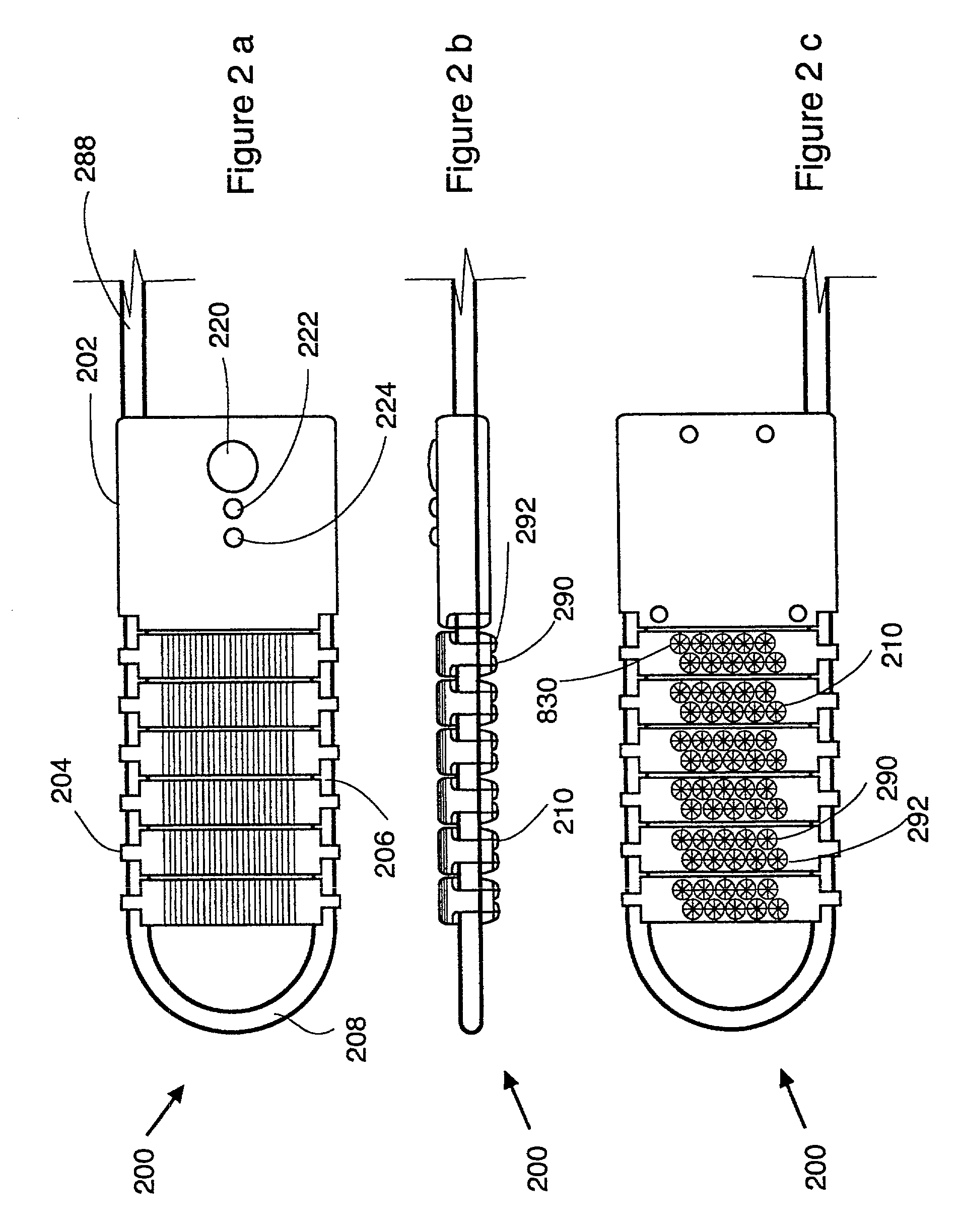
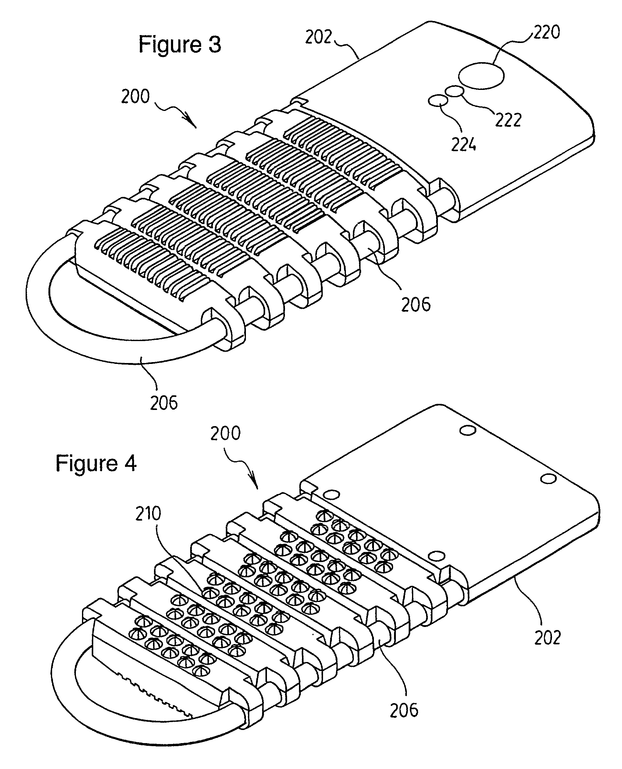
[0049] Several types of treatment heads are described in the following description. FIGS. 2(a), 2(b), 2(c), 3, 4 and 5(a)-(c) illustrate a flexible treatment head shown generally by numeral 200 primarily for treating large surface areas, while FIG. 7 illustrates a single source treatment head 700 generally referred to as a laser treatment head, which may be used for the treatment of numerous smaller regions or for stimulating acupuncture points. FIGS. 33-35 show a further embodiment of treatment head intended for personal use and FIG. 36 shows a head similar to FIGS. 33-35 with an enhanced interface.

[0050] In FIGS. 2(a)-(c), in which like numerals indicate similar structures, a flexible head is shown generally by numeral 200. The flexible head 200 includes a rectangular control pod 202 or housing which contains the main circuitry for controlling and powering diodes 210; and a plurality of diode carrying pockets 204 extending from one end of the control pod and threaded on a flexible...


PUM


Abstract

A photon therapy unit implement has a flexible head for conforming to a body part to be treated. The head has a thermally conductive backing to remove heat from the treatment area. The operation of the head is monitored by a photon detector to provide a feedback to the diode drive circuit to maintain the output at the required level. Operation of the head is monitored by a microprocessor which performs a diagnostic function and reports on defects. The treatment protocol is generated by a main control unit that formulates a treatment waveform from a set of treatment protocols. The selection of protocols is performed through a graphical user interface (GUI) which allows selection of treatment areas and customization of treatment as well as maintaining patient history and annotations.

Description

[0001] This invention relates to a photon therapy system, commonly referred to as a low intensity laser therapy system, wherein a substantial number of treatment parameters may be relatively accurately and consistently controlled.[0002] 1. Field of the Invention[0003] Photon therapy is used amongst others for the treatment of muscular skeletal disorders and wound healing. Photon therapy systems arm primarily administered by chiropractors, physiotherapists, sports therapists, and medical doctors in a clinical environment. Generally, photon therapy treatment is effected by applying light energy or photons in the visible and / or infrared regions to parts of the body. Strictly speaking, in photon therapy the light energy generated does not produce any significant heating effects but does invoke photochemical and photobiological effects in the biological tissue.[0004] 2. Description of the Prior Art[0005] While numerous photon therapy systems are in existence today, none provide a complet...

Claims


Application Information

Patent Timeline
Patent Type & Authority Applications(United States)
IPC IPC(8): A61N5/00A61N5/06
CPCA61B2017/00477A61B2017/00482A61N5/0616A61N5/0619A61N5/0622A61N2005/007A61N2005/0644A61N2005/0645A61N2005/0652A61N2005/067A61N5/067
Inventor VAN ZUYLEN, JEFFREYKAHN, FREDCAMPBELL, IAIN
Owner VAN ZUYLEN JEFFREY
Learn More