
Optical fiber with low macrobend loss at large bend diameter

a technology of optical fibers and macrobends, applied in the field of optical fibers and cables, can solve the problems of microbend loss, attenuation loss and bending loss, signal loss, etc., and achieve the effect of minimizing macrobend loss, minimizing macrobend loss, and low macrobend loss

Active Publication Date: 2022-11-22
CORNING INC
View PDF9 Cites 0 Cited by
  • Summary
  • Abstract
  • Description
  • Claims
  • Application Information

AI Technical Summary

Benefits of technology

This patent describes how to make optical fibers for use in submarine transmission systems. These fibers have a special design to minimize the loss of light when they are bent. This is important because bending is a common occurrence in these systems, and the loss of light can affect the quality of the signal being transmitted. The design of the fiber helps to reduce this loss by using a trench in the cladding, which reduces the space available for bending. The patent shows that reducing the volume of the trench results in less loss of light.

Problems solved by technology

The primary sources of signal loss are attenuation loss and bending loss.
Bend loss includes losses due to microbending and macrobending.
Microbending losses are caused by high frequency mechanical perturbations originating from external stimuli in the deployment environment of the optical fiber.
Macrobending losses are signal losses caused by bending or wrapping of the optical fiber.
The mechanical environment experienced by optical fiber deployed in submarine systems, however, differs from terrestrial applications and macrobend losses in particular are unreasonably high in submarine systems.

Method used


Image

  • Optical fiber with low macrobend loss at large bend diameter
  • Optical fiber with low macrobend loss at large bend diameter
  • Optical fiber with low macrobend loss at large bend diameter

Examples


examples

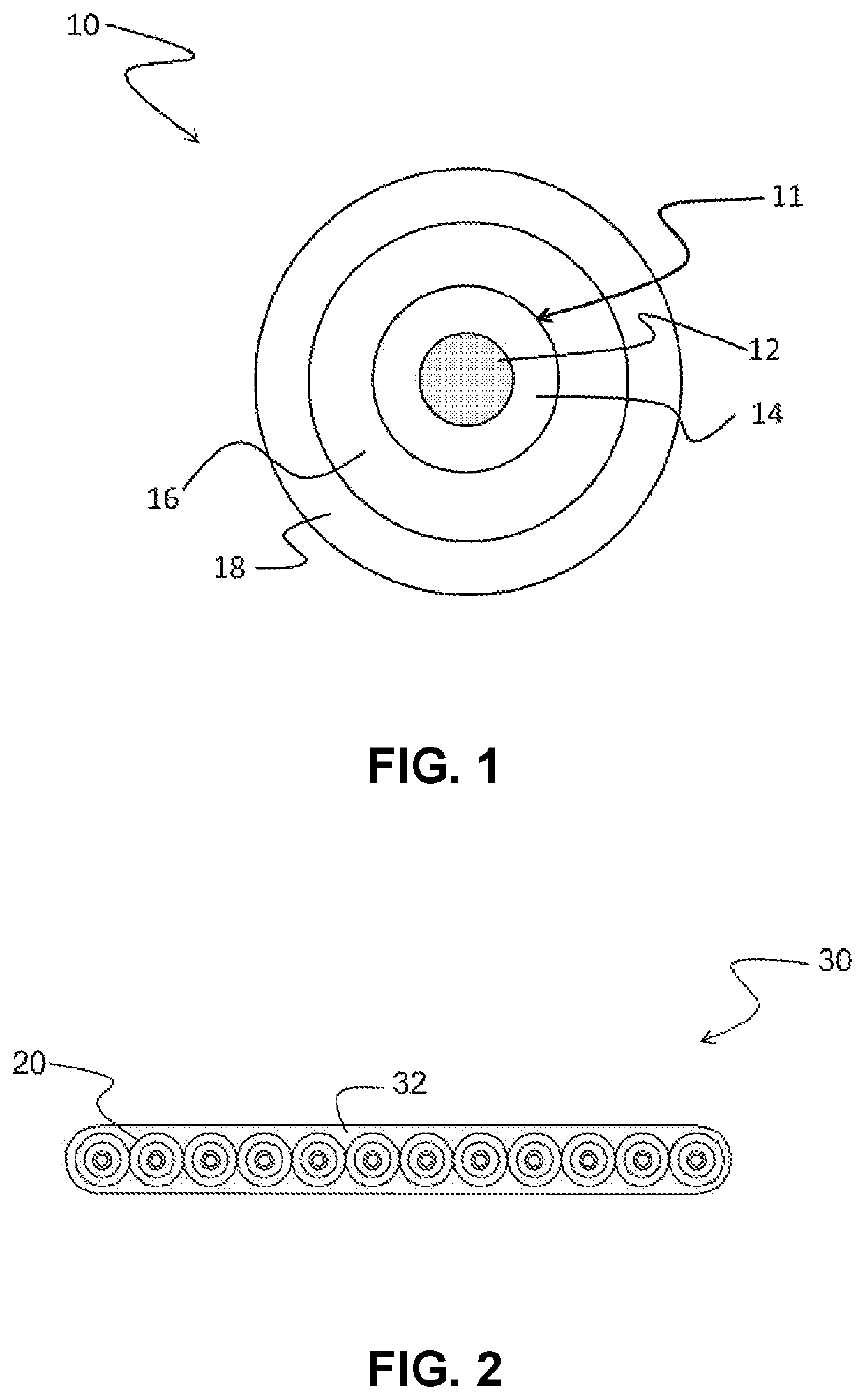
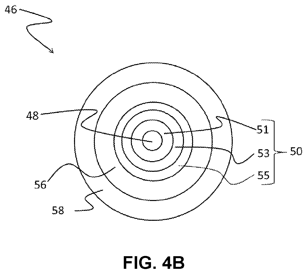
[0143]The following examples illustrate optical fibers having cladding regions with a trench cladding region configured to minimize macrobend losses at bend diameters greater than 40 mm. The trench cladding region of the illustrative optical fibers have a relative refractive index Δ3 and / or a thickness r3−r1 (in embodiments without an offset cladding region) or r3−r2 (in embodiments with an offset cladding region) configured to provide a trench volume conducive to minimizing macrobend losses at bend diameters greater than 40 mm.

[0144]Macrobending.

[0145]Macrobending loss was determined using the mandrel wrap test specified in the standard TIA-455-62: FOTP-62 IEC-60793-1-47 Optical Fibres—Part 1-47: Measurement Methods and Test Procedures—Macrobending Loss, by Telecommunications Industry Association (TIA). In the mandrel wrap test, the fiber is wrapped one or more times around a smooth cylindrical mandrel having a specified diameter, and the increase in attenuation at a specified wave...


PUM


Abstract

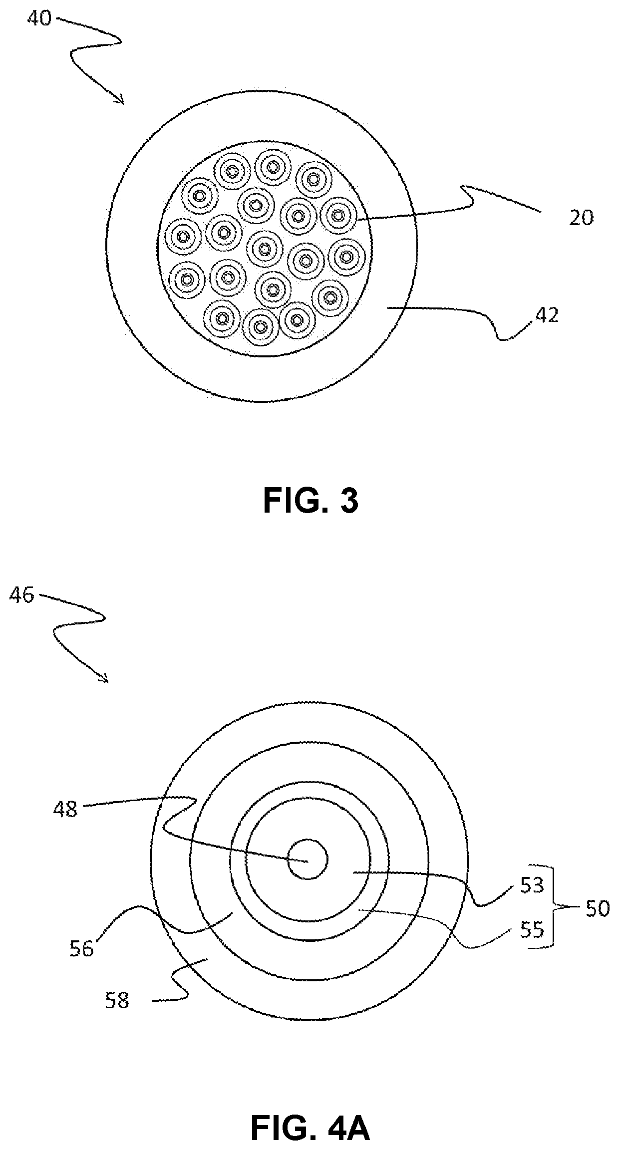
The present disclosure provides optical fibers that exhibit low macrobend loss at 1550 nm at bend diameters greater than 40 mm. The relative refractive index profile of the fibers includes a trench cladding region having a trench volume configured to minimize macrobend loss at large bend diameters. The thickness and / or depth of the trench cladding region are controlled to reduce trench volume to a degree consistent with reducing macrobend loss at bend diameters greater than 40 mm. The optical fiber includes an outer cladding region that surrounds and is directly adjacent to the trench cladding region and an optional offset cladding region between the trench cladding region and the core region. In some embodiments, the core region is a segmented core region that includes inner and outer core regions. The low macrobend loss available from the optical fibers makes them particularly suitable for applications in submarine telecommunications systems.

Description

[0001]This application claims the benefit of priority to U.S. Provisional Application Ser. No. 62 / 939,828 filed on Nov. 25, 2019 and to U.S. Provisional Application Ser. No. 62 / 945,930 filed on Dec. 10, 2019, the content of which is relied upon and incorporated herein by reference in its entirety.FIELD OF THE DISCLOSURE[0002]This disclosure pertains to optical fibers and cables. More particularly, this disclosure pertains to optical fibers and cables configured for submarine environments. Most particularly, this disclosure pertains to optical fibers and cables having low macrobend loss at large bend diameters.BACKGROUND OF THE DISCLOSURE[0003]Telecommunication systems require optical fibers capable of transmitting optical signals over long distances with low loss at high data rates. Transmission capacity has been improved through advances in wavelength division multiplexing and modulation formats. Wavelength division multiplexing increases the number of transmission channels, while ...

Claims


Application Information

Patent Timeline
Patent Type & Authority Patents(United States)
IPC IPC(8): G02B6/028G02B6/02
CPCG02B6/0281G02B6/02009G02B6/02342G02B6/02395G02B6/0365G02B6/03627
Inventor HEBGEN, PETER GOTTFRIEDMATTHEWS, III, HAZEL BENTONMISHRA, SNIGDHARAJ KUMAR
Owner CORNING INC
Learn More