Method for calibrating defective channels of a CT device

a ct device and defective technology, applied in the field of medical technologies, can solve the problems of inaccurate estimation, uneven performance, degrading clinical diagnosis,

Active Publication Date: 2022-11-22
MINFOUND MEDICAL SYST CO LTD
View PDF4 Cites 0 Cited by
  • Summary
  • Abstract
  • Description
  • Claims
  • Application Information

AI Technical Summary

Benefits of technology

[0006]An objective of the present invention is to provide a method for calibrating defective channels of a CT device that eliminates effects of artifacts caused by defective channels, and particularly defective channel clusters with a large area, on image reconstruction, thereby ensuring the quality of clinical diagnosis.
[0041]The present invention advantageously employs a neural network to perform training on data in areas to be recovered and thereby supplementing texture of the to-be-recovered area but not simply performing interpolation, so that the calculated values of attenuation of rays at the sites of defective channels are close to the actual values, thereby significantly improving the quality of image reconstruction and ensuring the quality of clinical diagnosis. With supplement to texture of areas to be recovered, accurate calculation of attenuation of rays can be ensured even if there are continuous defective channels.

Problems solved by technology

These channels tend to have uneven performance, which means some rays unable to properly respond to incidence become defective channels that lead to ring artifacts during image reconstruction, in turn degrading clinical diagnosis.
The first issue to be addressed is about inaccurate estimation of high-frequency information, which leading to streak artifacts with respect to some certain angles.
The second issue is that significant errors tend to happen in case of continuous damaged detectors, which brings about ring artifacts that are relatively pale.

Method used


Image

  • Method for calibrating defective channels of a CT device
  • Method for calibrating defective channels of a CT device
  • Method for calibrating defective channels of a CT device

Examples


Embodiment Construction

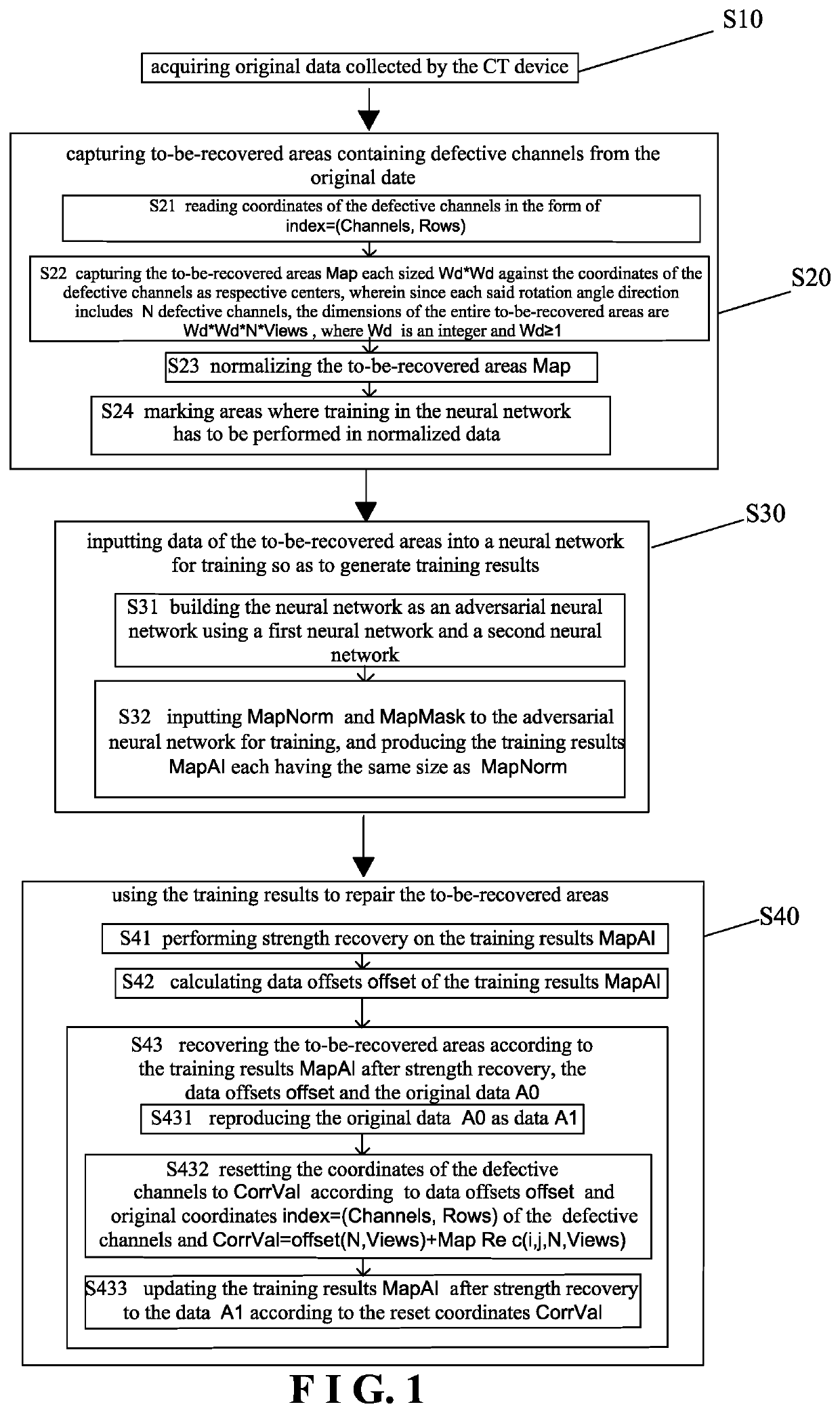
[0048]Referring to FIG. 1 through FIG. 5, a preferred embodiment of a method for calibrating defective channels of a CT device according to the present invention comprises the following steps:

[0049]in the step S10, acquiring original data collected by the CT device;

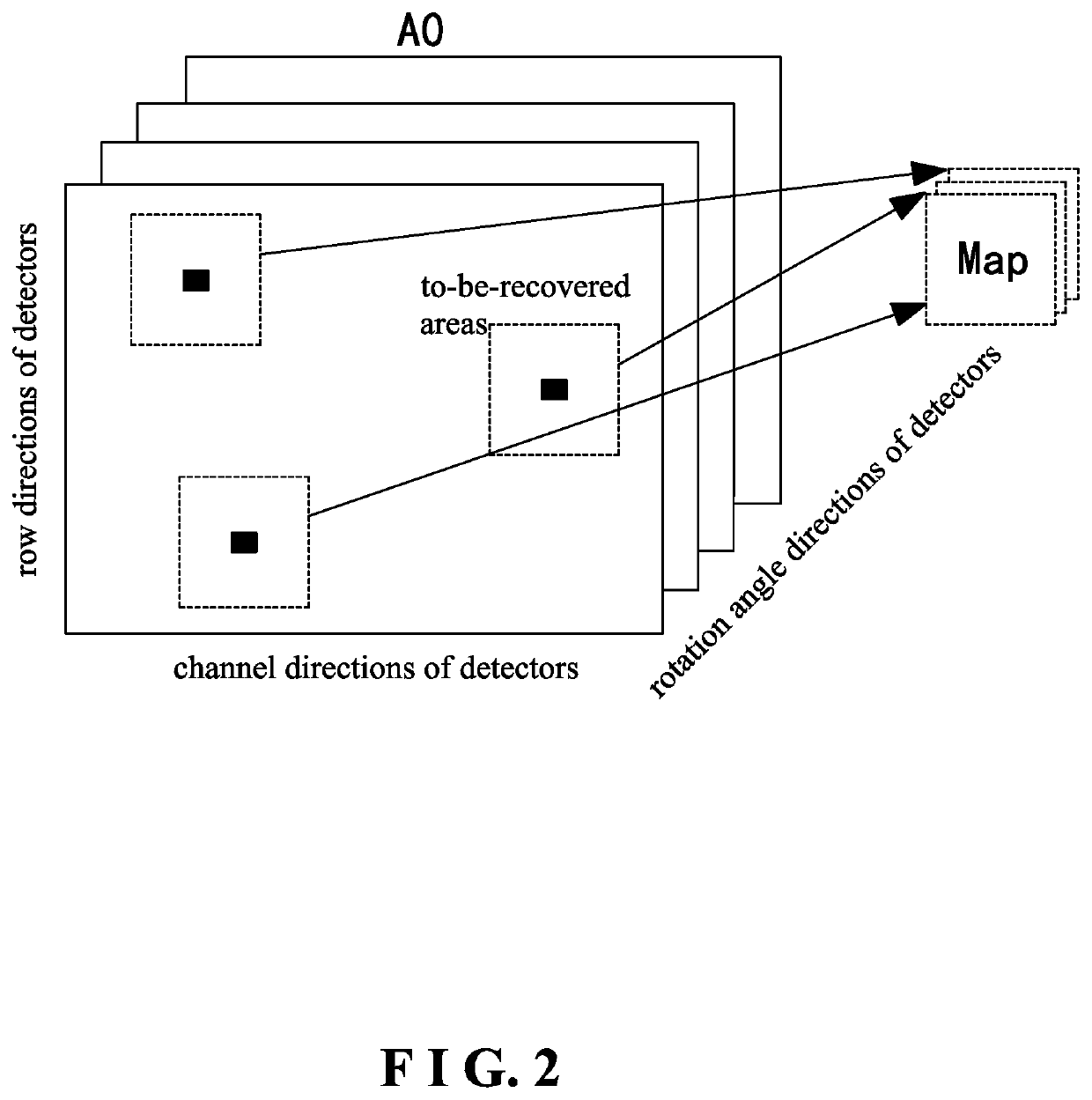
[0050]in the step S20, capturing to-be-recovered areas from the original data, wherein the to-be-recovered areas contain the defective channels of the CT device, in which the to-be-recovered area may be a single defective channel, or a defective channel cluster composed of multiple defective channels;

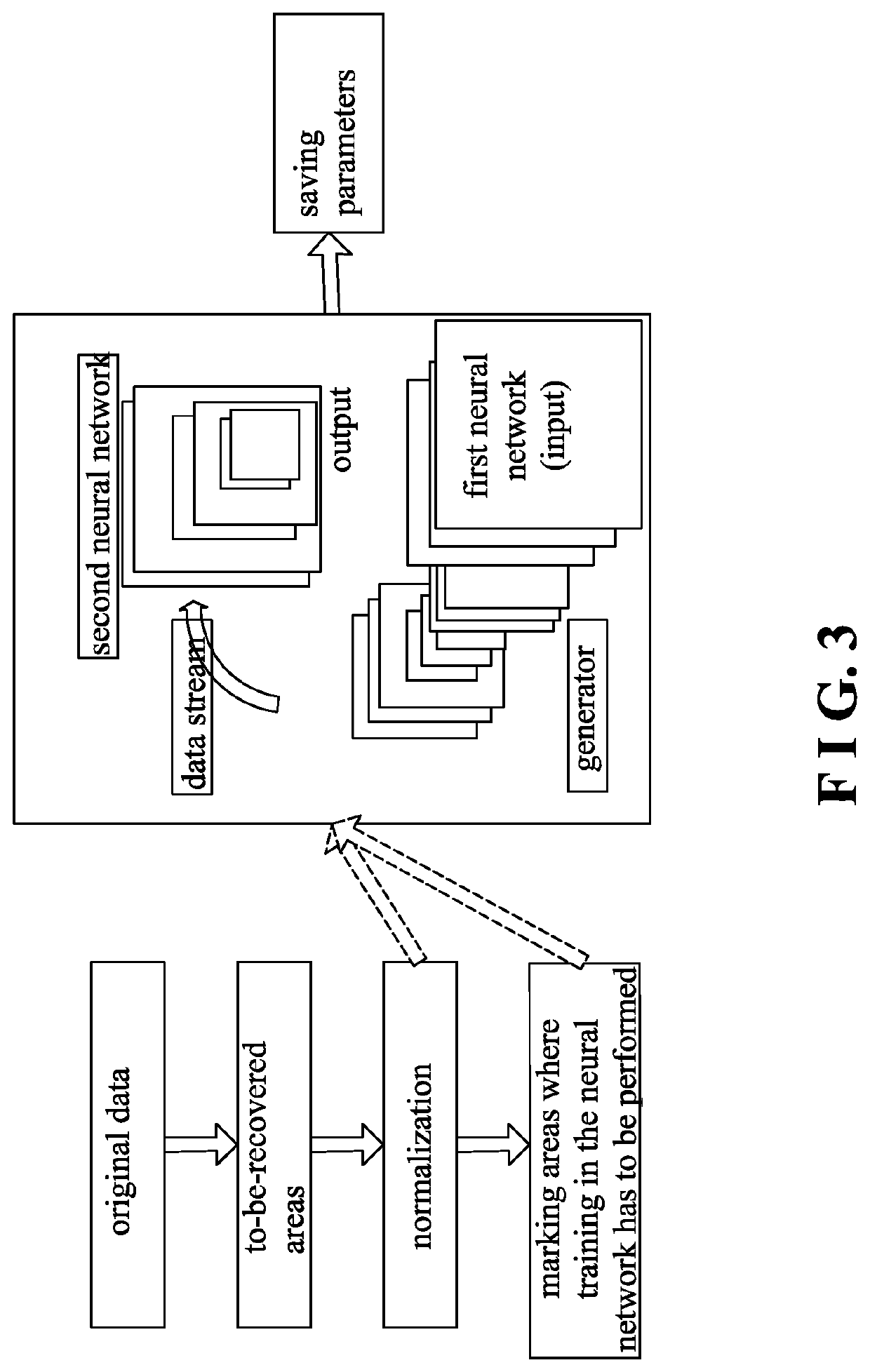
[0051]in the step S30, inputting data of the to-be-recovered areas into a neural network for training so as to produce training results; and

[0052]in the step S40, using the training results to repair the to-be-recovered areas.

[0053]The step S10 particularly is:

[0054]acquiring the original data collected by the CT device as three-dimensional data A0(Channels, Rows, Views), where Channels represents channel directions of detect...


PUM


Abstract

A method for calibrating defective channels of a CT device involves in a step S10, acquiring original data collected by the CT device; in a step S20, capturing to-be-recovered areas from the original data, wherein the to-be-recovered areas contain the defective channels of the CT device; in a step S30, inputting data of the to-be-recovered areas to a neural network for training so as to generate training results; and in a step S40, using the training results to repair the to-be-recovered areas. The method eliminates effects of artifacts caused by defective channels on image reconstruction.

Description

BACKGROUND OF THE INVENTION1. Technical Field[0001]The present invention relates to medical technologies, and more particularly to a method for calibrating defective channels of a CT device.2. Description of Related Art[0002]Computed tomography (CT) is a technology that uses precise, calibrated X rays, γ rays, and ultrasonic waves in conjunction with high-sensitivity detectors to perform scanning and produces section scans one by one around a certain part of a human body. With the ability to figure out the shape, structure and possible material of a scanned object using transmittance of rays (X rays, γ rays, and ultrasonic waves) at different angles, CT has the benefits about fast scanning and clear images, and is useful in detection of a wide range of diseases. A typical multi-detector CT device has channels (detectors) in an amount ranging from tens of thousands to hundreds of thousands. These channels tend to have uneven performance, which means some rays unable to properly respo...

Claims


Application Information

Patent Timeline
Patent Type & Authority Patents(United States)
IPC IPC(8): A61B6/00G01T7/00G06N3/08G06T5/00G06T11/00
CPCA61B6/585A61B6/42G01T7/005G06N3/08G06T5/001G06T11/005G06T2207/10081G06T2207/20081G06T2207/20084G06T5/005G06T11/008G06N3/045G01T1/2985A61B6/586G06N3/088G06N3/047G06T2211/441
Inventor IKHLEF, AZIZCHU, ZHENGWANG, YAOFA
Owner MINFOUND MEDICAL SYST CO LTD
Why Eureka
Try Eureka