Half-ring segment, connection clamp, and connection device

a technology of connection clamp and half-ring segment, which is applied in the direction of flanged joints, pipe joints, couplings, etc., can solve the problems of high manufacturing complexity required for such a tri-clamp and the inability to attach it to standard line sections

Active Publication Date: 2022-10-25
SARTORIUS STEDIM BIOTECH GMBH
View PDF13 Cites 1 Cited by
  • Summary
  • Abstract
  • Description
  • Claims
  • Application Information

AI Technical Summary

Benefits of technology

[0012]The task of the present invention is to refine a category-specific connection clamp, allowing more cost-effective manufacturing, thus making a single-use application more economical, and to achieve a sufficient and sealing clamping force of the contact flanges of the line sections to be coupled to one another possible without a need for additional tools or the use of screw-on nuts and clamping bolts as locking devices as is the case in conventional Tri-Clamp connections. In particular, it is the task of the invention to achieve this without modifying the additional (second) line section that is to be coupled to the first line section and is not actually part of the invention.
[0020]The half-ring segments according to the invention can be manufactured as simple injection-moulded parts made of plastic. Additional pre-assembly is not necessary, making production cheaper. In particular, in the preferred case where the connection clamp according to the invention is to be formed of two identically formed half-ring segments, further cost decreases will result.
[0028]In a first preferred variant of the connection device according to the invention, it is provided that the first threaded means are embodied as ramp sections that are distributed over the circumference of the connection piece, and that the slanted areas of said ramp sections are arranged on their sides facing away from the contact flange, and the second threaded means are embodied as ramp sections distributed correspondingly over the circumference of the connection clamp, with the slanted areas of said ramp sections being arranged on their sides facing the clamping flange. In such a manner, e.g., twin-start threads are realized, wherein each thread turn has the length of half a turn. The thread turns do not overlap. Thus, the connection clamp is rotatable a maximum of 180° with increasing torque. The advantage of this embodiment is the maximization of the contact surface between first and second threaded means, which contact one another over a wide area when tightened. This prevents deformations that might result in leaks, even if low-deformability plastic is used.
[0035]The person skilled in the art will have recognized in the context of the above explanations that, due to the required engagement of the first and second threaded means, closing the connection clamp so that it surrounds the clamping flanges of the pipe sections is not possible at all rotational angle positions of the connection clamp relative to the connection piece. Instead, this will typically only be possible at a rotational angle position from which a rotation in the tightening direction is possible. To permit this starting position to be found more easily, one preferred refinement of the invention provides that the connection piece has a first linear guide element extending in a tangential direction, and one of the half-ring segments has a corresponding second linear guide element on the interior wall or as a part of the wall of one of its segment ends. Firstly, these linear guide elements mark the rotational angle position in which the half-ring segments must be disposed relative to the connection piece in order to be able to latch onto one another. Secondly, these linear guide elements also limit the possible movements of the half-ring segments as a consequence of the linear pushing movement towards one another required for latching.
[0037]It can be advantageous when the linear guide element of the half-ring segment has a latching clamp at its front end. In its pre-assembly position, this latching clamp applies a clamping force on the linear guide element of the connection piece, thus restricting both axial movement and rotation of the half-ring segment relative to the connection piece.
[0041]It can be advantageous when an elastic resetting element is arranged on the interior side of the half-ring segment between the segment ends of a half-ring segment. This resetting element is designed such that the resetting element applies a resetting force on the half-ring segment, this resetting force countering the force necessary for moving the half-ring segments from a pre-assembly position to a final assembly position. Releasing the latching means thus permits the half-ring segments to be moved from a final assembly position into a pre-assembly position.

Problems solved by technology

What is disadvantageous is the high manufacturing complexity required for such a Tri-Clamp, which, in addition to providing two half-ring segments, also includes their pivotable, and yet preferably non-detachable, connection.
What is disadvantageous is that one of the two line sections to be coupled must have been pre-assembled before mounting it to the bell and its nut.
It is not possible to attach it to standard line sections after the fact, or to replace the connection clamp.

Method used


Image

  • Half-ring segment, connection clamp, and connection device
  • Half-ring segment, connection clamp, and connection device
  • Half-ring segment, connection clamp, and connection device

Examples


third embodiment

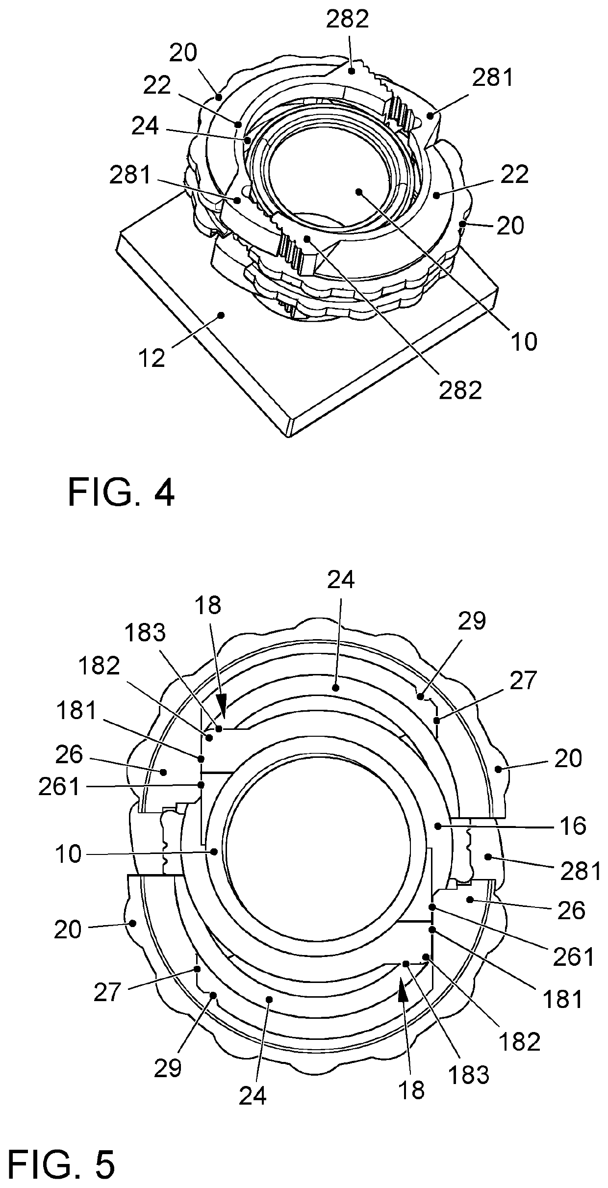
[0099]FIGS. 14 and 15 depict a connection piece 10″ and a half-ring segment 20″ according to a The guide wing 26″ of the half-ring segment 20′ has a linear guide element, e.g., a round-bolt-like linear guide edge 261″. Accordingly, the corresponding wing 18″ of the connection piece 10″ is equipped with a latching slot 181″ instead of a simple linear guide edge 181, so that secure retention in the pre-assembly position is assured.

[0100]In addition, instead of the safety latching boss 29 of the half-ring segment 20 of the first embodiment, provided in the third embodiment is a latching rocker 29″ whose latching hook 291″ latches into a corresponding latching recess of the connection piece 10″ in the final position. Due to the rocker-type design of this type of safety latching means, the latch can be manually released, if necessary, by applying manual pressure on the release lever 293″ arranged on the other side of the rocker axle 292″.

[0101]Apart from this, what has been described in...

fifth embodiment

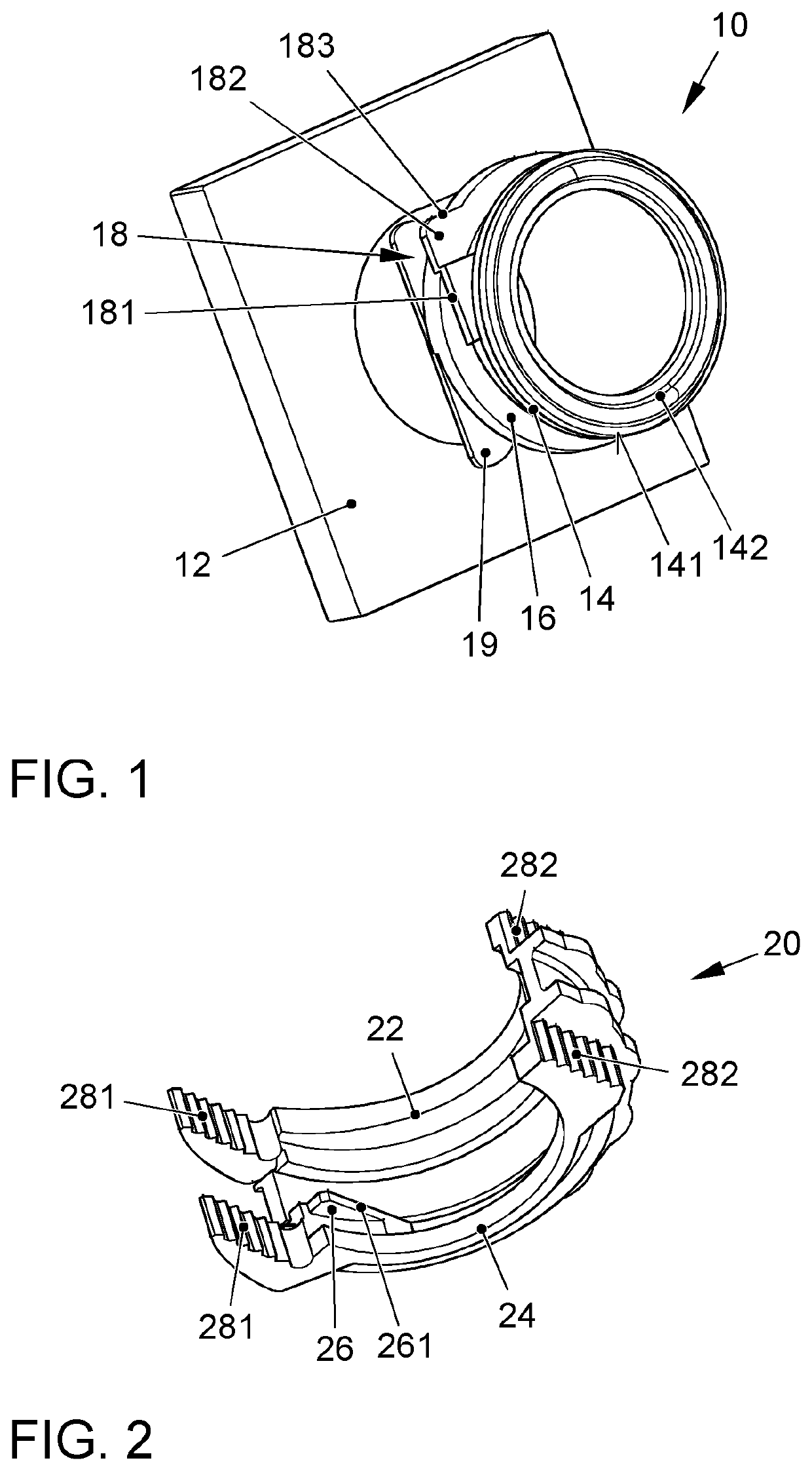
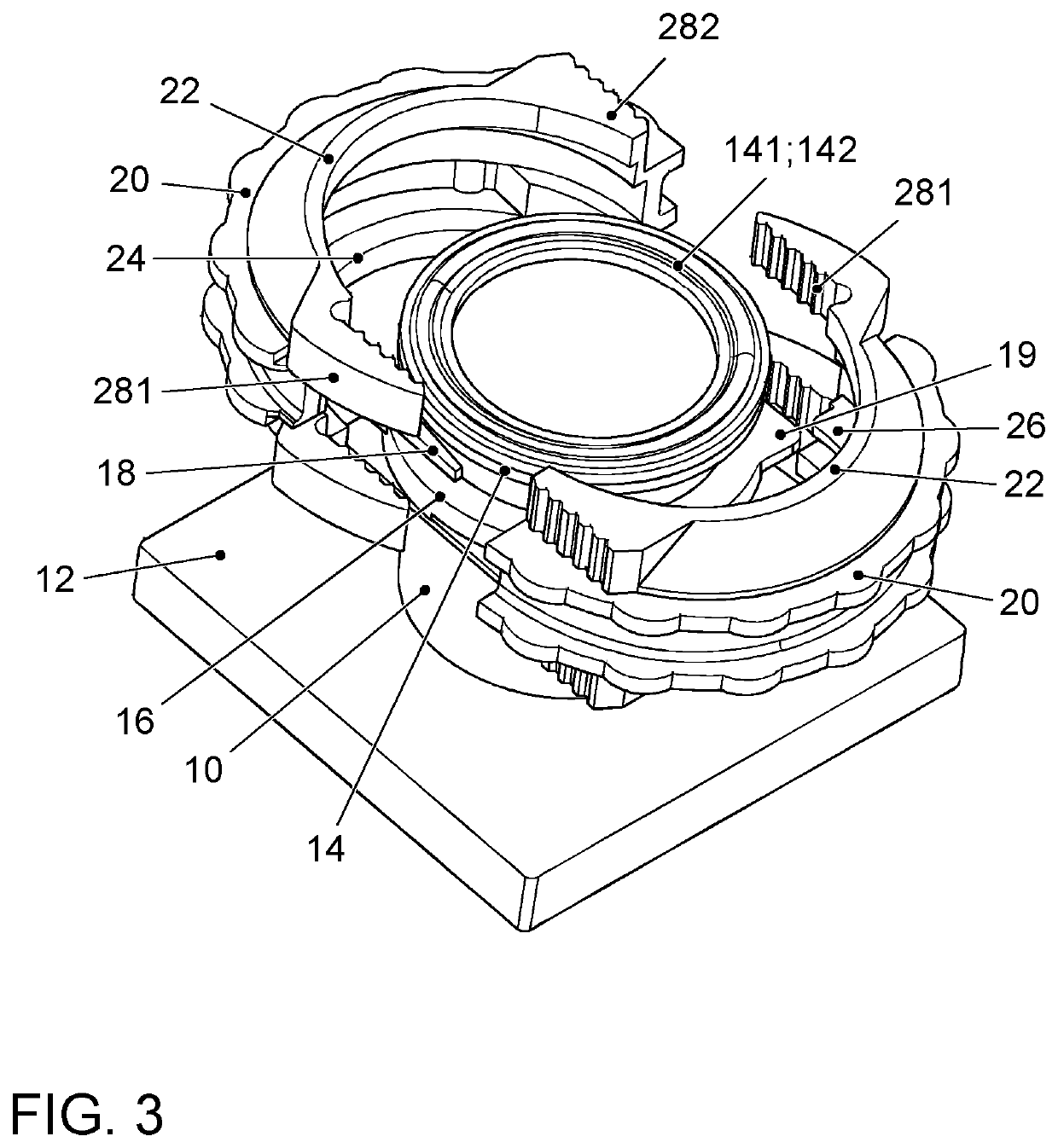
[0104]FIGS. 18 through 27 depict a connection piece 10″″ and an associated half-ring segment 20″″ according to the invention.

[0105]FIG. 18 depicts a connection piece 10″″ having a first threaded means 161″″ on its exterior. The first threaded means 161″″ comprises two local holding lugs projecting radially outwards that are arranged diametrically opposing one another on the exterior of the connection piece 10″″. In addition to the first threaded means 161″″, two linear guide elements 181″″ are arranged on the exterior of the connection pieces 10″″ and are also embodied as local holding lugs projecting radially outwards and are at least largely located in a plane with the first threaded means 161″″. The first threaded means 161″″ forms an angle of approximately 90° with the linear guide elements 181′″.

[0106]FIG. 19 depicts a perspective front view (FIG. 19a)) and a perspective rear view (FIG. 19b)) of a half-ring segment according to the invention 20″″ that is suited for use with a c...

sixth embodiment

[0121]FIGS. 28 through 37 depict a connection piece 10′″″ and the associated half-ring segments 201′″″, 202′″″ according to the invention.

[0122]FIG. 28 depicts a connection piece 10′″″ in an additional embodiment of the invention. The connection piece 10′″″ differs significantly from the connection piece 10″″ in FIG. 18 in that no threaded means are arranged on the exterior of the connection piece 10′″″.

[0123]FIG. 29 depicts, in a perspective front view (FIG. 29b)) and a perspective rear view (FIG. 29a)), an inventive first half-ring segment 201′″″ suited for use with a connection piece 10′″″ according to FIG. 28.

[0124]The half-ring segment 201′″″ depicted in FIG. 29 has, on both segment ends of the half-ring segment 201″″, latching means 281″″ that extend in a tangential direction and are in the form of latching tabs with a latching hook 294′″″ oriented radially outwards. These latching means are latching means of the first type.

[0125]In addition, the depicted half-ring segment 201...


PUM

PropertyMeasurementUnit
angleaaaaaaaaaa
rotationaaaaaaaaaa
circumferenceaaaaaaaaaa

Abstract

The invention relates to an annular connection clamp with a first clamping flange (22) which protrudes radially inwards and with an axial counter bearing (24) which is spaced from the clamping flange and which is made of a first and a second half-ring segment (20), each half-ring segment having a first and a second segment end. The first segment end of the first half-ring segment (20) has latching means (281) of a first type, and the second segment end of the second half-ring segment has corresponding latching means (282) of a second type, said latching means being pushed into each other in a tangential direction, thereby being latchable together. The second segment end of the half-ring segment (20) has latching means (282) of a second type, and the first segment end of the second half-ring segment (20) has latching means (281) of a first type, said latching means being pushed into each other in a tangential direction, thereby being latchable together.

Description

CROSS-REFERENCE TO RELATED APPLICATIONS[0001]This application is a National Phase Application of PCT International Application No. PCT / EP2017 / 060812, International Filing Date May 5, 2017, claiming priority of German Patent Application No. 10 2016 108 905.2, filed May 13, 2016, which is hereby incorporated by reference.DESCRIPTIONField of the Invention[0002]The invention relates to an annular connection clamp having a first clamping flange protruding radially inwards and an axial counter bearing spaced axially from said clamping flange and formed of a first and a second half-ring segment, each half-ring segment having a first and a second segment end, wherein the first segment end of the first half-ring segment has latching means of a first type and the second segment end of the second half-ring segment has corresponding latching means of a second type which are pushed into one another in a tangential direction, thereby being latchable together.[0003]The invention further relates to...

Claims


Application Information

Patent Timeline
Patent Type & Authority Patents(United States)
IPC IPC(8): F16L37/12F16L47/14F16L23/04F16L23/22
CPCF16L37/1225F16L23/04F16L47/14F16L23/22
Inventor AUE, NORBERTHANDT, SEBASTIANPURMANN, SEBASTIANLIMPERT, VOLKER
Owner SARTORIUS STEDIM BIOTECH GMBH
Why Eureka
Try Eureka