Heat-wing
a technology of heat exchanger and wing, which is applied in the direction of heat exhanger fins, basic electric elements, lighting and heating apparatus, etc., can solve the problem that the heat pipe tends to reach the heat transfer limi
- Summary
- Abstract
- Description
- Claims
- Application Information
AI Technical Summary
Benefits of technology
Problems solved by technology
Method used
Image
Examples
first embodiment
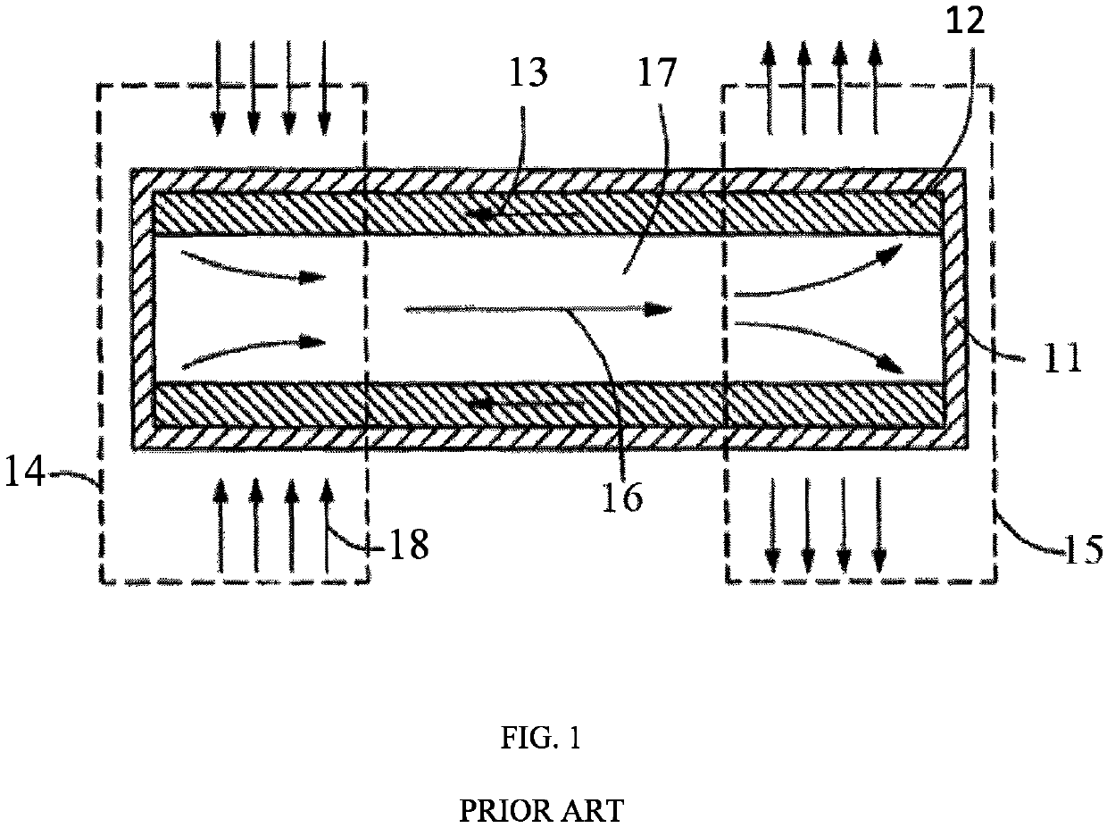
[0043]the present invention is shown in FIGS. 3 and 4. As illustrated, the heat-wing of the present invention includes a chamber 2 which is essentially a hollow plate-shaped structure including the first plate 20, the second plate 21 and a second portion 22 of the frame and a first portion 23 of the frame connecting the two plates (20 and 21). The heat-wing further includes a capillary structure layer 12 which is closely attached to an inner surface of the chamber 2, and a phase transition working medium 13 hermetically sealed in the chamber 2. The first outside surface portion of the frame 23 comes in contact with a heat source 3, and thus functions as an evaporation area, while the rest portion of the chamber 2 acts as a condensation area. Alternatively, it is also possible to use a portion of a periphery of one of the first plate 20 and the second plate 21 to serve as the evaporation area.
[0044]Each of a length and a height of the heat-wing is much greater than a thickness of the...
seventh embodiment
[0058]FIG. 10 shows the present invention. As illustrated, in this embodiment, a plurality of the heat-wings of FIG. 3 are arranged in an array and disposed on a heat source, totally covering the top surface of the heat source. Such array arrangement expands the two-dimensional phase-change heat transfer into a three-dimensional space and hence can achieve a higher heat flux density.
[0059]FIGS. 11 and 12 show an eighth embodiment of the present invention. As illustrated, in this embodiment, a plurality of the J-shaped heat-wings of FIG. 7 are arranged in an array and disposed on a heat source, totally covering the top surface of the heat source. Differing from the seventh embodiment, each heat-wing of the array of this embodiment is bent to project laterally from the heat source and is thus particularly suitable for applications where there exists a height limitation.
ninth embodiment
[0060]FIG. 13 shows a three-dimensional view of a heat-wing array in accordance with the present invention.
PUM
 Abstract
Description
Claims
Application Information
 - Generate Ideas
- Intellectual Property
- Life Sciences
- Materials
- Tech Scout
- Unparalleled Data Quality
- Higher Quality Content
- 60% Fewer Hallucinations
Browse by: Latest US Patents, China's latest patents, Technical Efficacy Thesaurus, Application Domain, Technology Topic, Popular Technical Reports.
© 2025 PatSnap. All rights reserved.Legal|Privacy policy|Modern Slavery Act Transparency Statement|Sitemap|About US| Contact US: help@patsnap.com


