
Broadband antenna having polarization dependent output

a polarization-dependent, broadband technology, applied in the field of antennas, can solve the problems of high coupling between different polarization directions, difficult fabrication of geometries, and inability to provide beam steering or dual-polarization operation

Active Publication Date: 2022-09-06
TECH UNIV MUNCHEN
View PDF4 Cites 0 Cited by
  • Summary
  • Abstract
  • Description
  • Claims
  • Application Information

AI Technical Summary

Benefits of technology

The solution provides a scalable, efficient, and readily fabricable antenna array with low cross-polarization, enabling broad bandwidth and beam steering capabilities suitable for 5G frequencies, improving data rates and energy efficiency.

Problems solved by technology

The known antenna geometries can however be difficult to fabricate, may not provide beam steering or dual-polarized operation or may suffer from high coupling between different polarization directions, low frequency, low bandwidth, or low efficiency.

Method used


Image

  • Broadband antenna having polarization dependent output
  • Broadband antenna having polarization dependent output
  • Broadband antenna having polarization dependent output

Examples


Embodiment Construction

[0056]The features and numerous advantages of the antenna according to the present invention will best be understood from a detailed description of preferred embodiments with reference to the accompanying drawings, in which:

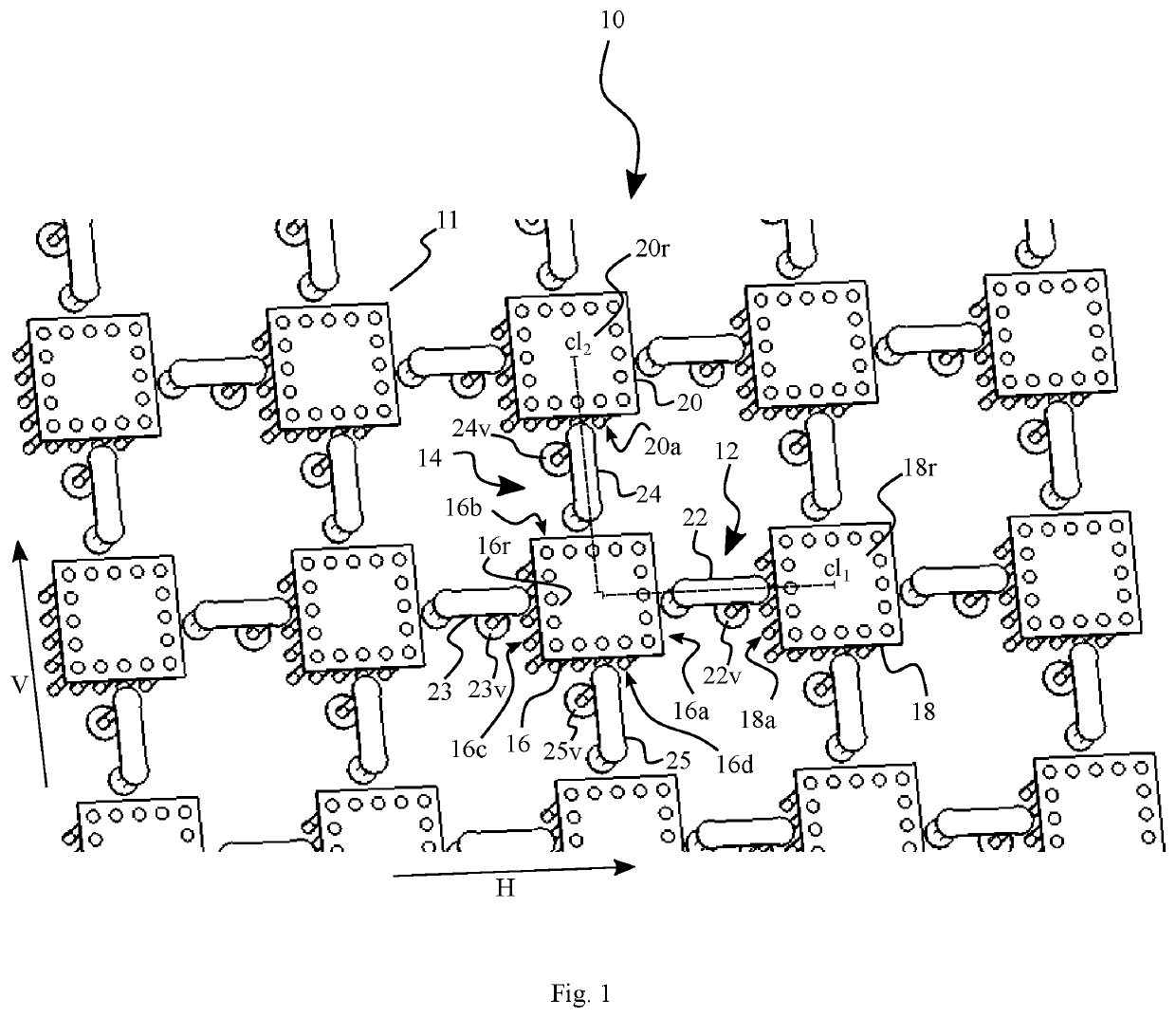
[0057]FIG. 1 is a schematic perspective view of an antenna according to an example;

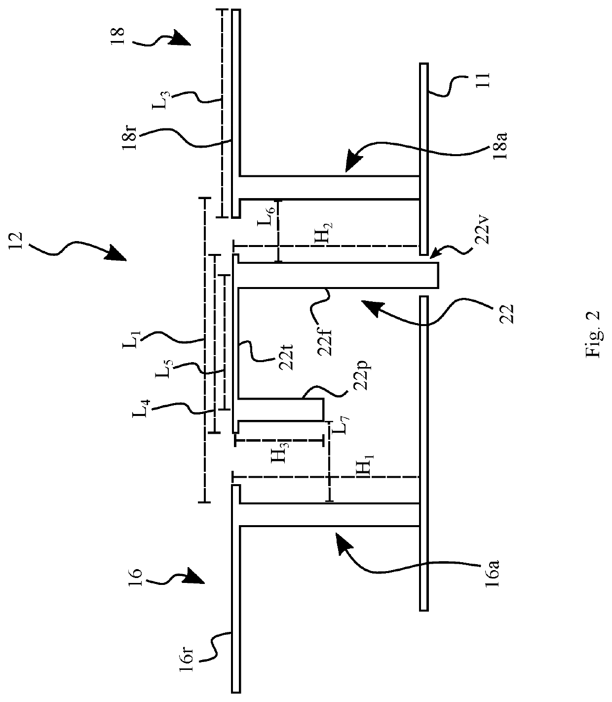
[0058]FIG. 2 is a schematic side view of an antenna according to an example;

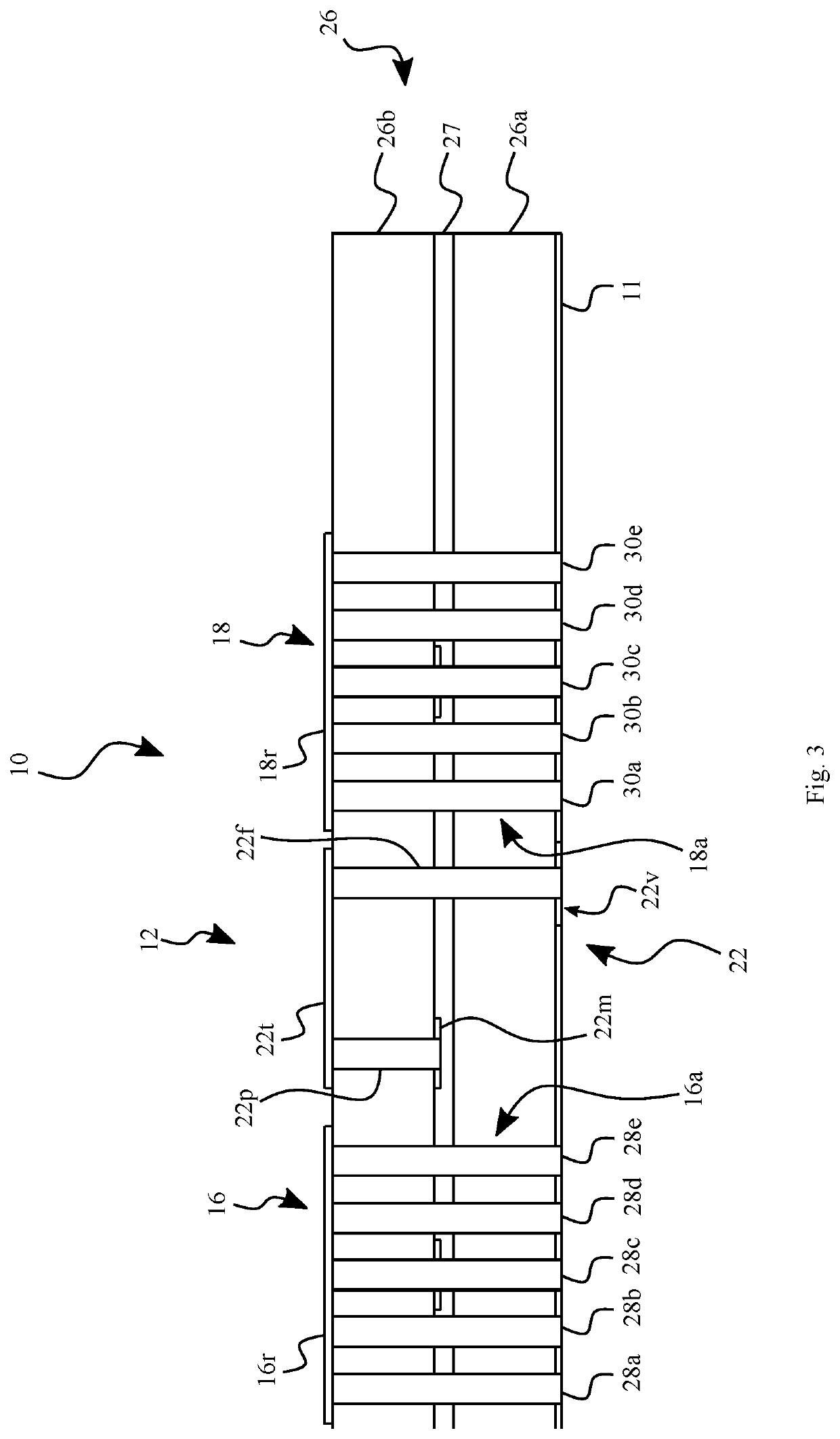
[0059]FIG. 3 is a schematic illustration of an antenna element fabricated in a substrate according to an example;

[0060]FIG. 4 is a schematic top view of an antenna according to an example;

[0061]FIG. 5A illustrates a set of S-Parameters for an antenna according to an example;

[0062]FIG. 5B illustrates simulated values of a co-polarization of an antenna according to an example; and

[0063]FIG. 5C illustrates simulated values of a cross-polarization of an antenna according to an example.

[0064]FIG. 1 shows an antenna 10 with a plurality of antenna elements, including first and second antenna elements 12, 14, arran...


PUM


Abstract

An antenna comprises a ground plane, a first antenna element and a second antenna element, wherein the first antenna element and the second antenna element are arranged for emitting and / or receiving electromagnetic radiation at a design wavelength with a first polarization direction and a second polarization direction, respectively, the second polarization direction being different from the first polarization direction, wherein the first and second antenna elements each comprise pairs of resonator elements having sidewalls facing a corresponding probe arranged in each pair of resonator elements, wherein one resonator element of each pair of resonator elements is shared between the first and second antenna elements and the respective probes of the first and second antenna elements are arranged on different sides of the shared resonator element.

Description

FIELD OF THE INVENTION[0001]The present invention is in the field of antennas. More precisely, the present invention relates to an antenna array having polarization dependent output and beam steering capabilities for possible 5G applications.BACKGROUND[0002]Modern information exchange is increasingly based on free space electromagnetic wave transfer between communicating parties. The growing demand for higher data transfer rates and the rising number of participants drives an ongoing development in radiofrequency technology towards higher frequencies and higher bandwidth.[0003]Antennas are used to send and receive signals encoded in electromagnetic waves and to provide an interface between electromagnetic waves propagating in free space and on-chip electronics for information processing, such as in base stations or mobile terminals. This interface often constitutes a bottleneck for the available frequencies for data transmission.[0004]To meet the requirements of next-generation comm...

Claims


Application Information

Patent Timeline
Patent Type & Authority Patents(United States)
IPC IPC(8): H01Q21/24H01Q21/06H01Q1/48H01Q9/04
CPCH01Q21/24H01Q1/48H01Q9/0407H01Q21/062H01Q21/065H01Q9/065H01Q1/241H01Q1/38H01Q21/0006
Inventor TOPRAK, ZAFER
Owner TECH UNIV MUNCHEN
Learn More