Motor driving circuit, integrated circuit device, and electronic apparatus
a technology of integrated circuit and motor, which is applied in the direction of dc motor rotation control, dc and a multiple dc dynamo-electric motor control, etc., and can solve problems such as analog circuit malfunction
- Summary
- Abstract
- Description
- Claims
- Application Information
AI Technical Summary
Benefits of technology
Problems solved by technology
Method used
Image
Examples
first embodiment
[0019
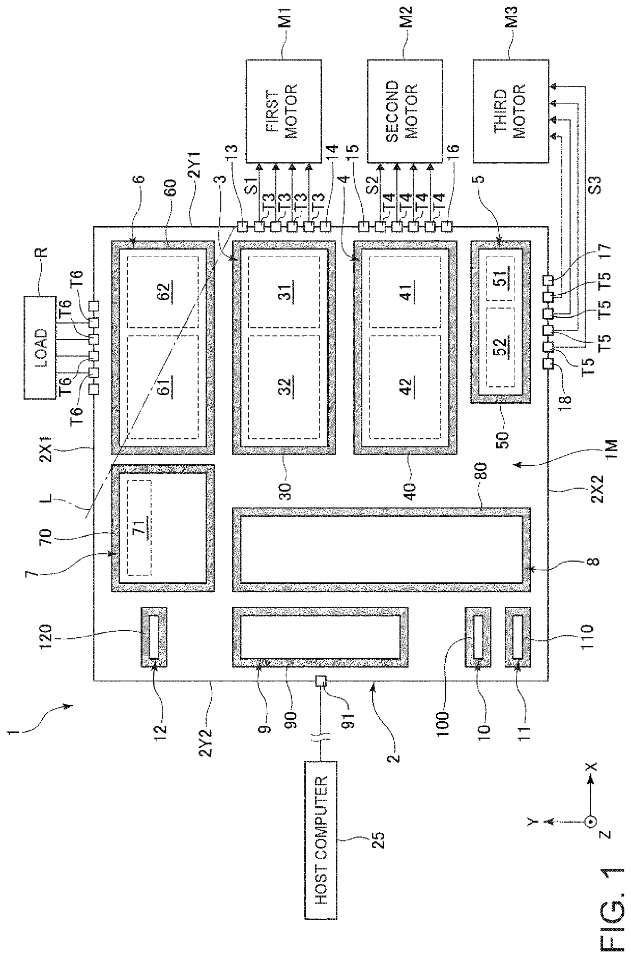
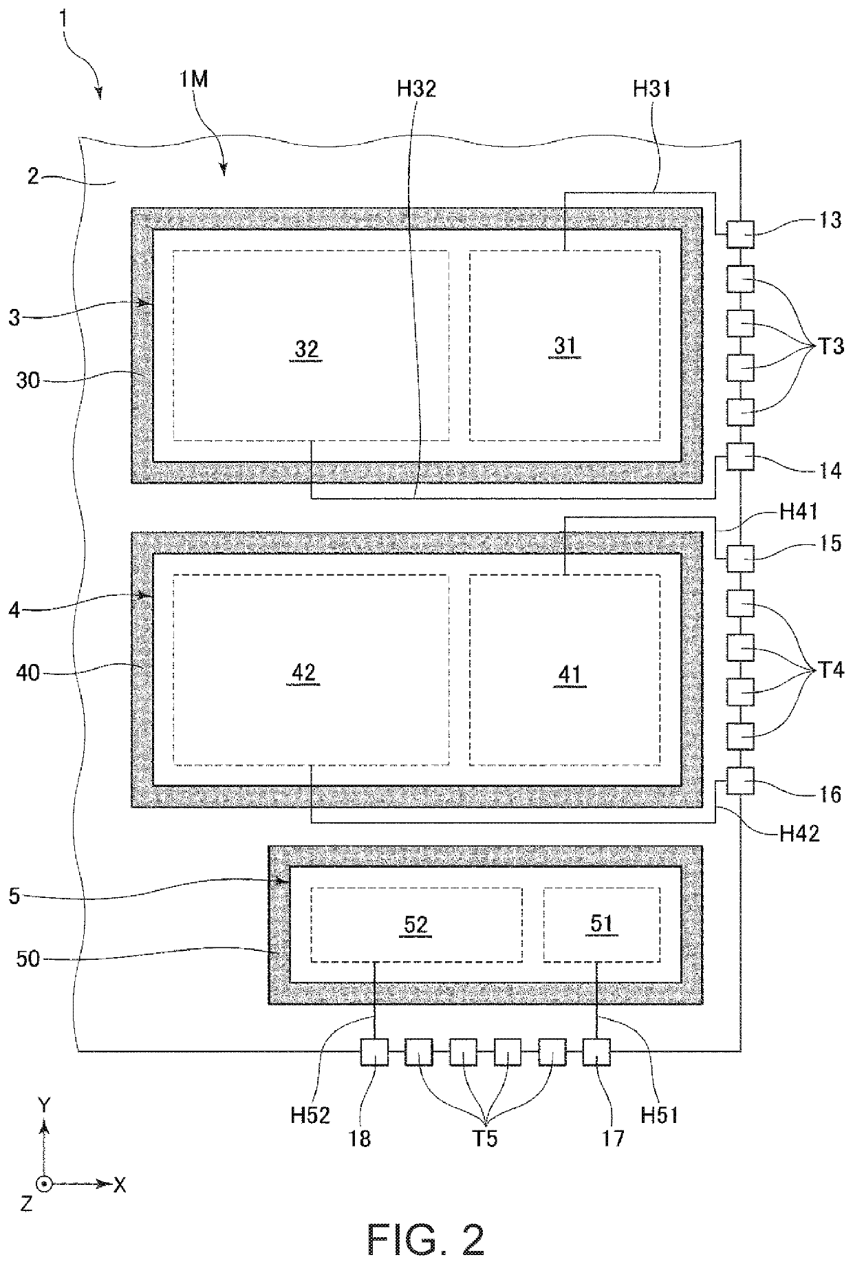
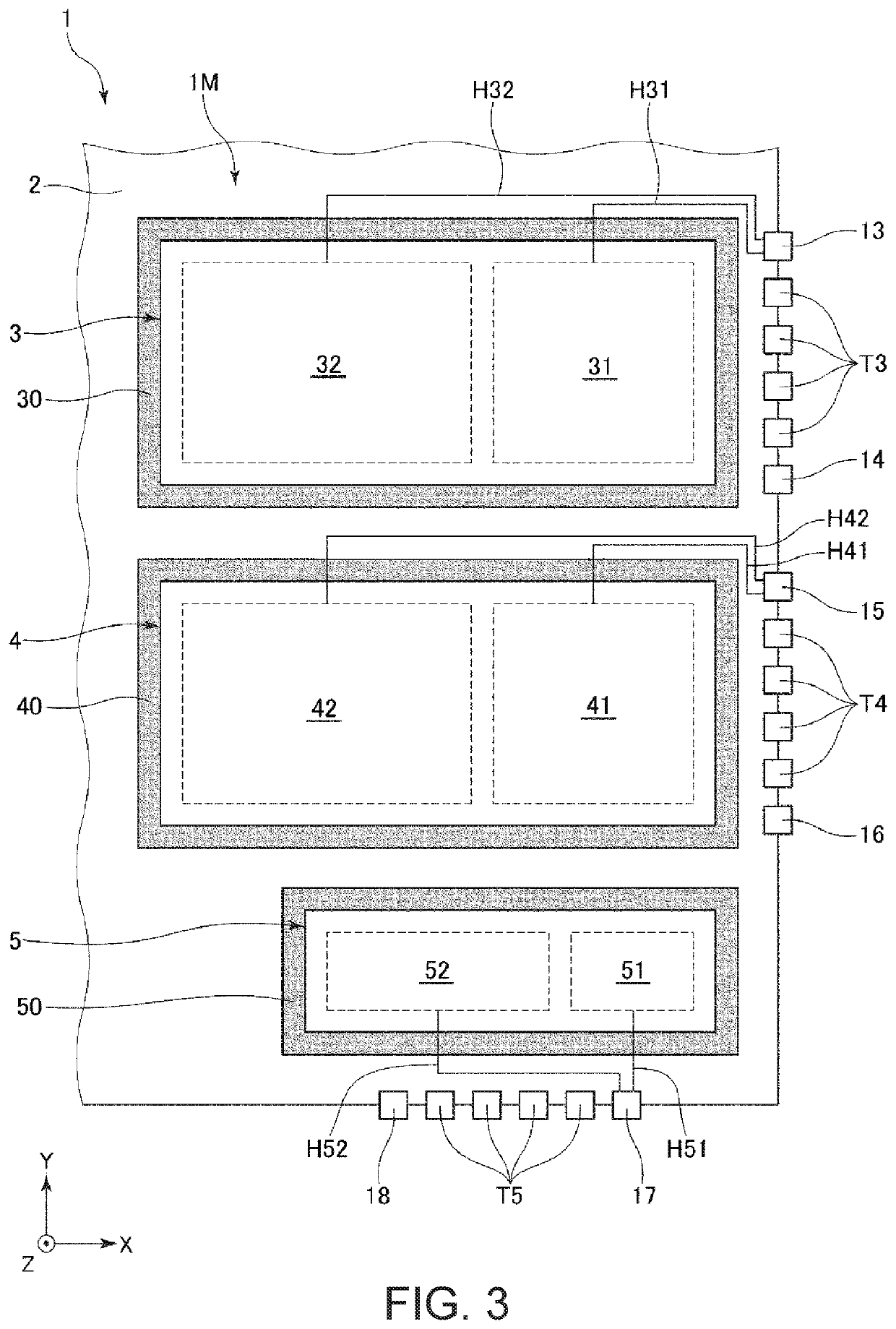
[0020]FIG. 1 is a diagram showing a circuit configuration of an integrated circuit device according to a first embodiment. FIGS. 2 and 3 are partial enlarged views of the integrated circuit device shown in FIG. 1. Note that, for convenience of description, FIGS. 1 to 3 show three axes orthogonal to each other, namely an X axis, a Y axis, and a Z axis. In addition, hereinafter, the front-edge side of the arrow of each axis is also referred to as a “plus side”, and the opposite side is also referred to as a “minus side”.
[0021]An integrated circuit device 1 shown in FIG. 1 is configured such that an IC chip in which a motor driving circuit 1M is formed on a silicon substrate 2, which is a semiconductor substrate, is housed in a package (not illustrated). The shape of the silicon substrate 2 when seen in a planar view from the Z axis direction is rectangular, and includes sides 2X1 and 2X2 that extend in the X axis direction and sides 2Y1 and 2Y2 that extend in the Y axis direction...
second embodiment
[0070
[0071]FIG. 4 is a block diagram showing an image reading device according to a second embodiment.
[0072]As shown in FIG. 4, an image reading device 1000 that is an electronic apparatus is a flatbed image reading device, and includes a paper feed device 1100, a carriage 1200, a carriage conveyance mechanism 1300, and a controller 1400 that performs various types of processing for reading an image.
[0073]The paper feed device 1100 includes a paper feed tray (not illustrated), a conveyance roller (not illustrated) for conveying a document placed on the paper feed tray to a document stage, and a DC motor 1110 for driving the conveyance roller. As a result of driving the DC motor 1110, and rotationally driving the conveyance roller, the document placed on the paper feed tray is conveyed to the document stage using the conveyance roller.
[0074]The carriage 1200 is disposed below the document stage. Also, an LED light source 1210 that illuminates the document on the document stage, and a...
third embodiment
[0077
[0078]FIG. 5 is a diagram showing an overall configuration of a projector according to a third embodiment. FIG. 6 is a diagram showing an overall configuration of an illumination device.
[0079]As shown in FIG. 5, a projector 2000 that is an electronic apparatus includes an illumination device 2100, a color separation light-guiding optical system 2200, the liquid crystal light modulating device 2300R, a liquid crystal light modulating device 2300G, a liquid crystal light modulating device 2300B, a cross dichroic prism 2600, and a projection optical system 2700. In addition, the illumination device 2100 includes a first illumination device 2110 and a second illumination device 2120. The first illumination device 2110 emits illumination light RG that includes red light and green light toward the color separation light-guiding optical system 2200. The second illumination device 2120 emits blue light B toward the color separation light-guiding optical system 2200.
[0080]As shown in FI...
PUM
 Abstract
Description
Claims
Application Information
 - R&D
- Intellectual Property
- Life Sciences
- Materials
- Tech Scout
- Unparalleled Data Quality
- Higher Quality Content
- 60% Fewer Hallucinations
Browse by: Latest US Patents, China's latest patents, Technical Efficacy Thesaurus, Application Domain, Technology Topic, Popular Technical Reports.
© 2025 PatSnap. All rights reserved.Legal|Privacy policy|Modern Slavery Act Transparency Statement|Sitemap|About US| Contact US: help@patsnap.com


