
Method of controlling a microgrid, power management system, and energy management system

a micro-grid and power management technology, applied in adaptive control, process and machine control, instruments, etc., can solve problems such as power imbalance, limited optimization that is achieved, and inability to achieve optimalization

Active Publication Date: 2022-07-26
HITACHI ENERGY SWITZERLAND AG
View PDF10 Cites 0 Cited by
  • Summary
  • Abstract
  • Description
  • Claims
  • Application Information

AI Technical Summary

Benefits of technology

The patent text discusses the need for methods, devices, systems, and microgrids that can better handle incorrect forecast variable values and provide enhanced robustness. The techniques described in the text can update the operating point of multiple assets in the microgrid to compensate for a deviation of a forecast variable value from its actual value. This can help to ensure that the total power provided by the microgrid is not significantly different from the desired target power, even if there are incorrect barometric readings or other uncertainties in the forecast. The patent also suggests that the increased computational complexity and bandwidth requirements associated with processing at the control system level may be moderate. Overall, the techniques described in the patent can improve the reliability and resilience of microgrids in the face of uncertainties in the weather and other external factors.

Problems solved by technology

In such a case, the optimization that is attained may be limited because the PMS only knows local values and has only past and present-time data.
However, when one or several forecast variable values are incorrect, i.e., the actual values differ from the forecast variable values, the calculated operating point vector is typically also incorrect.
This may result in power imbalance or the risk of non-optimal operation.
In particular, the calculated operating point vector would often result in a total power generation that is offset from a desired target power generation or power consumption of the controllable assets in the microgrid, if the forecast variables are incorrect.
The increase in computational complexity of the processing that is done at the EMS is moderate.

Method used


Image

  • Method of controlling a microgrid, power management system, and energy management system
  • Method of controlling a microgrid, power management system, and energy management system
  • Method of controlling a microgrid, power management system, and energy management system

Examples


Embodiment Construction

[0095]Exemplary embodiments of the invention will be described with reference to the drawings in which identical or similar reference signs designate identical or similar elements. While some embodiments will be described in the context of exemplary charging infrastructure concepts and / or exemplary on-board battery concepts, the embodiments are not limited thereto. The features of embodiments may be combined with each other, unless specifically noted otherwise.

[0096]Embodiments of the invention may be used to provide enhanced robustness in the control of a microgrid against possibly incorrect forecast variable values that are used to determine operating point values for controllable assets in the microgrid.

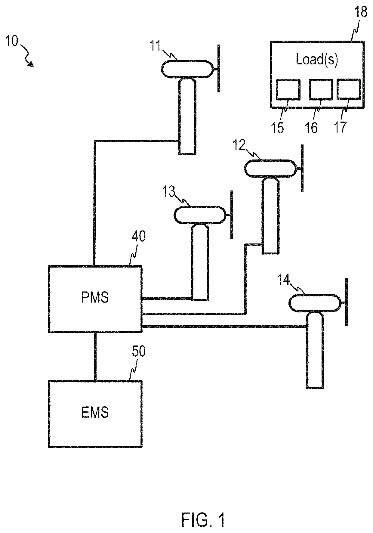
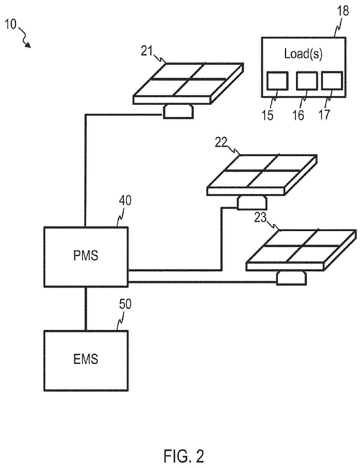
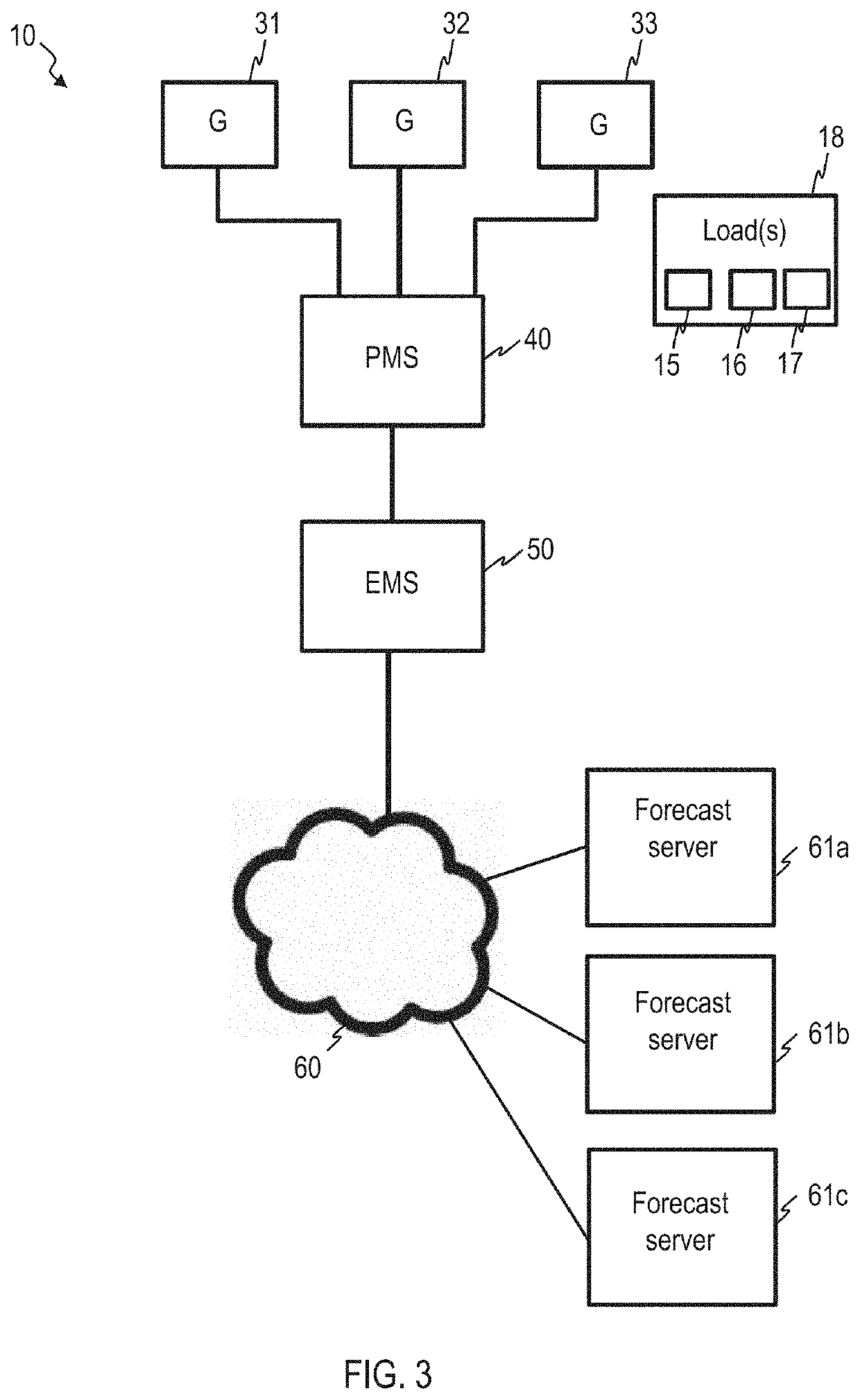
[0097]FIG. 1 shows an exemplary microgrid 10, which comprises a plurality of controllable power-generating assets 11, 12, 13, 14. The microgrid 10 may further comprise one or several loads 18, which may comprise one or several controllable loads 15, 16, 17. The one or several cont...


PUM


Abstract

A method of controlling a microgrid includes retrieving, by an energy management system, EMS, a forecast variable value for a forecast variable. The EMS determines an operating point value for a controllable asset that depends on the retrieved forecast variable value. The EMS determines an operating point shift value for the controllable asset, the operating point shift value representing a shift in operating point value in response to a variation in forecast variable value. The operating point value and the operating point shift value are provided to a power management system, PMS, of the microgrid.

Description

FIELD OF THE INVENTION[0001]Embodiments of the invention relate to methods, devices and systems for controlling a microgrid. Embodiments of the invention relate in particular to methods, devices and systems that use one or several forecast variables to determine operating points for controllable assets of a microgrid, such as controllable power-generating assets and / or controllable loads of a microgrid.BACKGROUND OF THE INVENTION[0002]A microgrid is a localized group of generators and loads. Control strategies for microgrids are getting increasingly important, also due to the increasing use of renewable energy sources (RES) or other systems with distributed energy generators (DEG). Control techniques for microgrids are described in, e.g., IEEE 2030.7-2017.[0003]A microgrid control system may be a Power Management System (PMS) that can coordinate a plurality of individual controllable power-generating assets and discretionary load (DL) assets in a predefined way. The Operating Point ...

Claims


Application Information

Patent Timeline
Patent Type & Authority Patents(United States)
IPC IPC(8): H02J3/00G05B13/04H02J3/38
CPCH02J3/003G05B13/048H02J3/381H02J2300/24H02J2300/28H02J3/46H02J3/14H02J2203/20H02J2300/20H02J2310/10Y04S40/20Y02B70/3225Y04S20/222Y02P80/14
Inventor TUCKEY, ANDREWBACCINO, FRANCESCO
Owner HITACHI ENERGY SWITZERLAND AG
Learn More