Image forming apparatus

Active Publication Date: 2022-07-26
FUJIFILM BUSINESS INNOVATION CORP
View PDF6 Cites 0 Cited by
  • Summary
  • Abstract
  • Description
  • Claims
  • Application Information

AI Technical Summary

Benefits of technology

The patent describes an image forming apparatus which includes several sections for forming an image on a surface. However, sometimes the image may not be properly transferred to the desired medium and there may be some residual charge left on the surface of the image holding section. The invention provides a way to eliminate this residual charge using an exposure static elimination section and a transfer static elimination section depending on the level of the residual charge. This helps to ensure that the image is properly transferred and there is no residual charge left on the surface of the image holding section.

Problems solved by technology

However, aspects of the non-limiting embodiments are not required to address the advantages described above, and aspects of the non-limiting embodiments of the present disclosure may not address advantages described above.

Method used


Image

  • Image forming apparatus
  • Image forming apparatus
  • Image forming apparatus

Examples


exemplary embodiment 1

[0045]Hereinafter, the present disclosure will be described in detail based on the exemplary embodiments illustrated in accompanying drawings.

[0046]Overall Configuration of Image Forming Apparatus

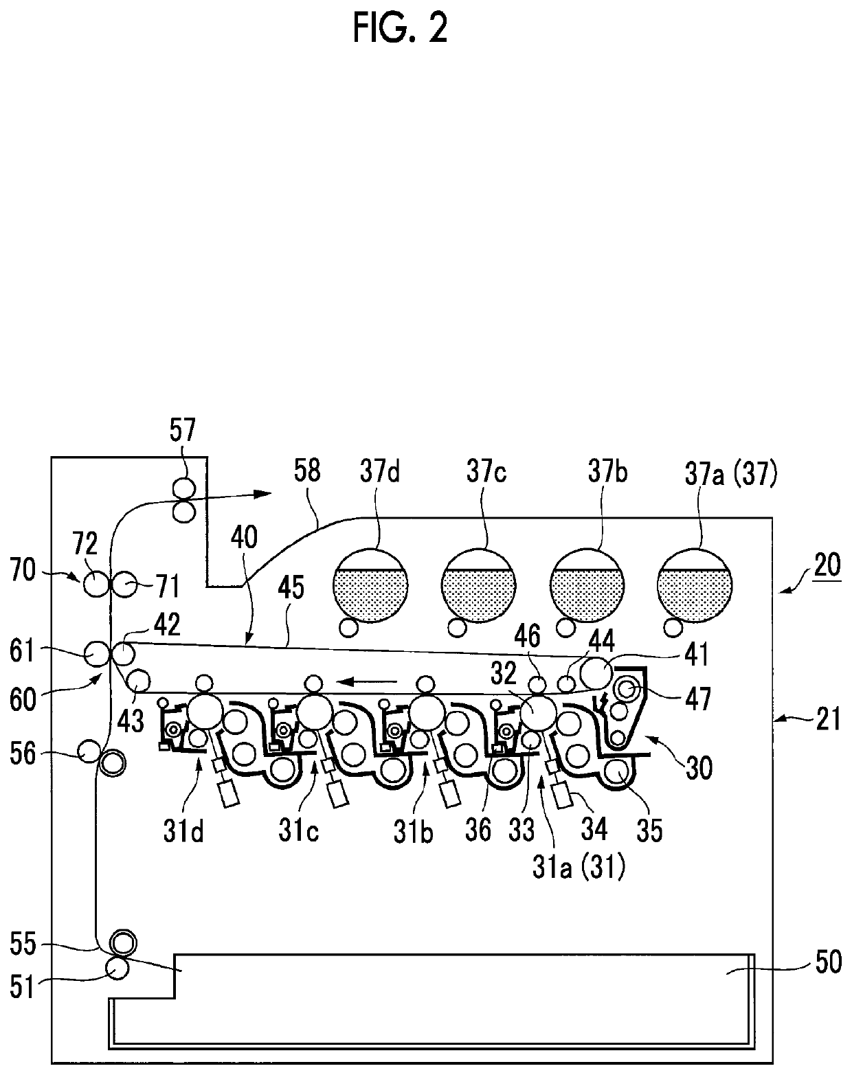
[0047]FIG. 2 is an explanatory diagram illustrating an overall configuration of an image forming apparatus according to Exemplary Embodiment 1.

[0048]In FIG. 2, in an image forming apparatus 20, an image forming engine 30 that forms an image of a plurality of colors (four colors of yellow, magenta, cyan, and black in the present exemplary embodiment) is mount in an apparatus housing 21, a recording material supply apparatus 50 that accommodates recording materials such as paper is disposed below the image forming engine 30, and a recording material transporting path 55 from the recording material supply apparatus 50 is disposed in a substantially vertical direction.

[0049]In the present example, in the image forming engine 30, image forming units 31 (specifically, 31a to 31d) that forms the i...


PUM


Abstract

An image forming apparatus includes: an image holding section that includes a photoconductor having a surface protection layer; a charging section that charges a surface of the image holding section with a direct current potential; an exposure section that exposes the surface of the image holding section charged by the charging section to form an electrostatic latent image; a developing section that develops the electrostatic latent image formed on the image holding section; a transfer section that electrostatically transfers a visible image formed on the image holding section to a transfer medium; an exposure static elimination section that eliminates a residual charge of the image holding section by using the exposure section when image formation on the image holding section is stopped; a transfer static elimination section that eliminates the residual charge of the image holding section by using at least the transfer section when the image formation on the image holding section is stopped; and a switching section that causes the exposure static elimination section to perform static elimination under a condition that the residual charge of the image holding section does not exceed a threshold value of an allowable static elimination level at which the residual charge is eliminated by the exposure static elimination section, and causes the transfer static elimination section instead of the exposure static elimination section to perform static elimination under a condition that the residual charge exceeds the threshold value.

Description

CROSS-REFERENCE TO RELATED APPLICATIONS[0001]This application is based on and claims priority under 35 USC 119 from Japanese Patent Application No. 2021-087570 filed May 25, 2021.BACKGROUND(i) Technical Field[0002]The present invention relates to an image forming apparatus.(ii) Related Art[0003]In the related art, for example, image forming apparatuses described in JP2016-206597A, and JP2013-228491A are previously known.[0004]In JP2016-206597A, a first mode, in which a toner is less likely to adhere to a developing sleeve and a second mode, in which wasteful toner consumption due to fog is suppressed is switched based on information that affects a toner charging amount, and static on a surface of an image carrier is eliminated, so that a potential of the image carrier is forcibly lowered. As a result, in particular, a technology of suppressing toner adhesion to the developing sleeve and suppressing the wasteful toner consumption even in a case of a direct current (DC) charging metho...

Claims


Application Information

Patent Timeline
IPC IPC(8): G03G21/06G03G15/16
CPCG03G21/06G03G15/1675G03G15/0291G03G21/08
Inventor YAMAGISHI, KAZUNARI
Owner FUJIFILM BUSINESS INNOVATION CORP
Why Eureka
Try Eureka