
Free-sliding seabed mudmat foundation

a technology of mudmat and seabed, which is applied in the direction of protective foundations, constructions, and caissons, can solve the problems of large increase in installation costs, large accumulation of excess pore water pressure and soil strain softening, and complex interaction between mudmat and seabed, so as to reduce transportation and installation costs, reduce fabrication costs, and the effect of small siz

Active Publication Date: 2022-07-26
DALIAN UNIV OF TECH
View PDF11 Cites 0 Cited by
  • Summary
  • Abstract
  • Description
  • Claims
  • Application Information

AI Technical Summary

Benefits of technology

The present invention is regarding a new type of foundation for use in offshore pipeline structures. This foundation is smaller in size than conventional mudmats, reducing fabrication costs. It can be transported and installed using a pipeline laying vessel, saving on transportation and installation costs. The top part of the foundation is designed to slide, releasing horizontal push force due to heating and pressurization, while the base remains stable to prevent disturbance of the seabed soil. This reduces the axial load on the pipeline and reduces the risk of buckling failure. The foundation also includes a damping device to reduce vibration and disturbance of the seabed soil. In summary, the new foundation design is cost-effective, easy to install, and efficient in reducing disturbances to the seabed.

Problems solved by technology

If the size of the mudmat is too large to meet the loading or hoisting capacity of the pipeline laying vessel, an additional large installation vessel is required for specially installing the mudmat.
This will significantly increase the installation cost.
The sliding process will result in the accumulation of the excess pore water pressure and the strain-softening of the soil.
Therefore, the mudmat-seabed interaction is very complex.
Moreover, the mudmat is subjected to moment and torsion caused by the horizontal push force generated by the pipeline due to heating and pressurization, causing the mudmat to rotate or tilt.
Under extreme conditions, the joint point between the pipeline and the subsea infrastructure even fails.

Method used


Image

  • Free-sliding seabed mudmat foundation
  • Free-sliding seabed mudmat foundation
  • Free-sliding seabed mudmat foundation

Examples


Embodiment Construction

[0036]For illustrative purposes, some of the presently preferred embodiments of the invention will now be described, with reference to the drawings.

1. Free-Sliding Subsea Mudmat Foundation

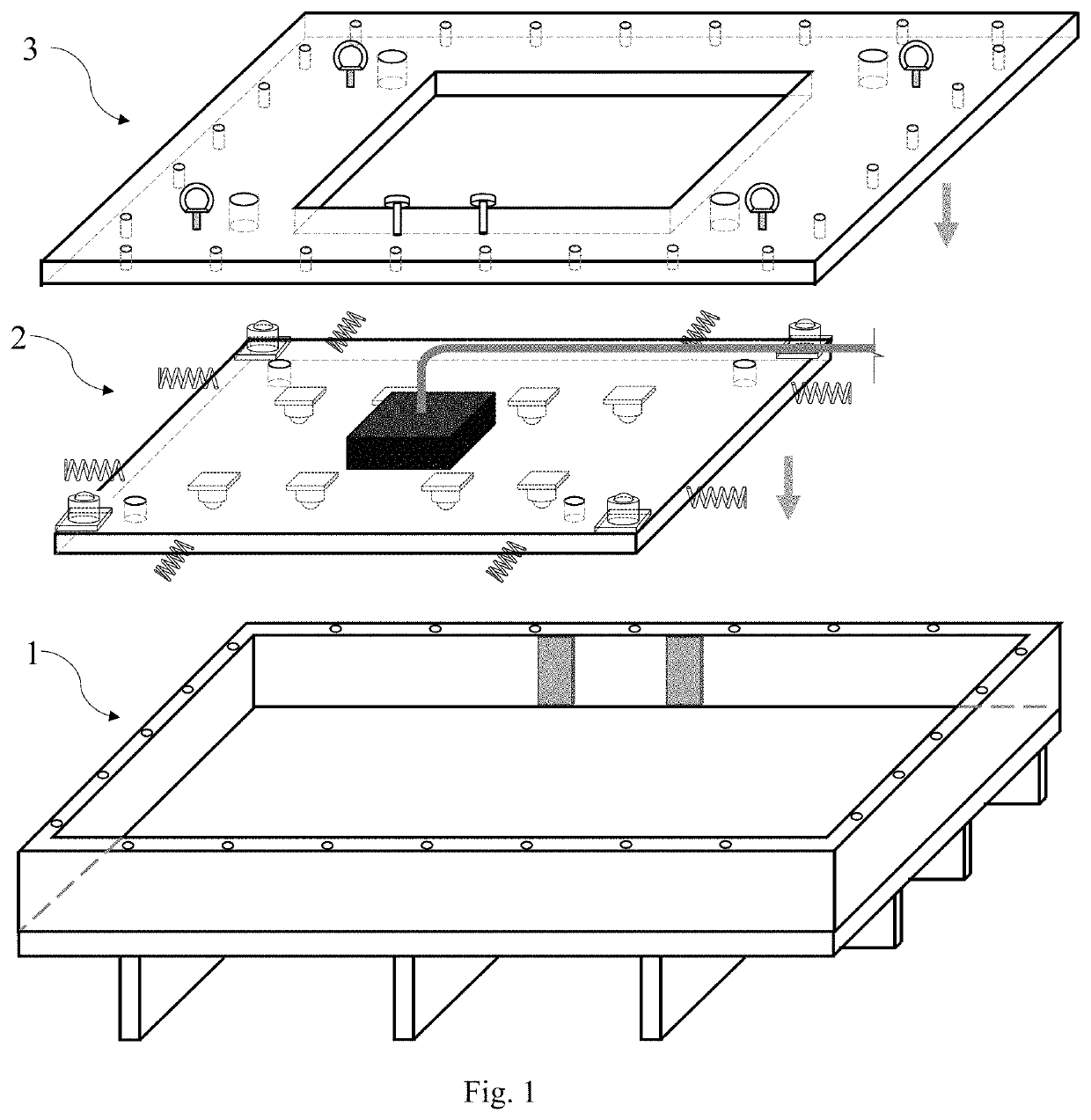
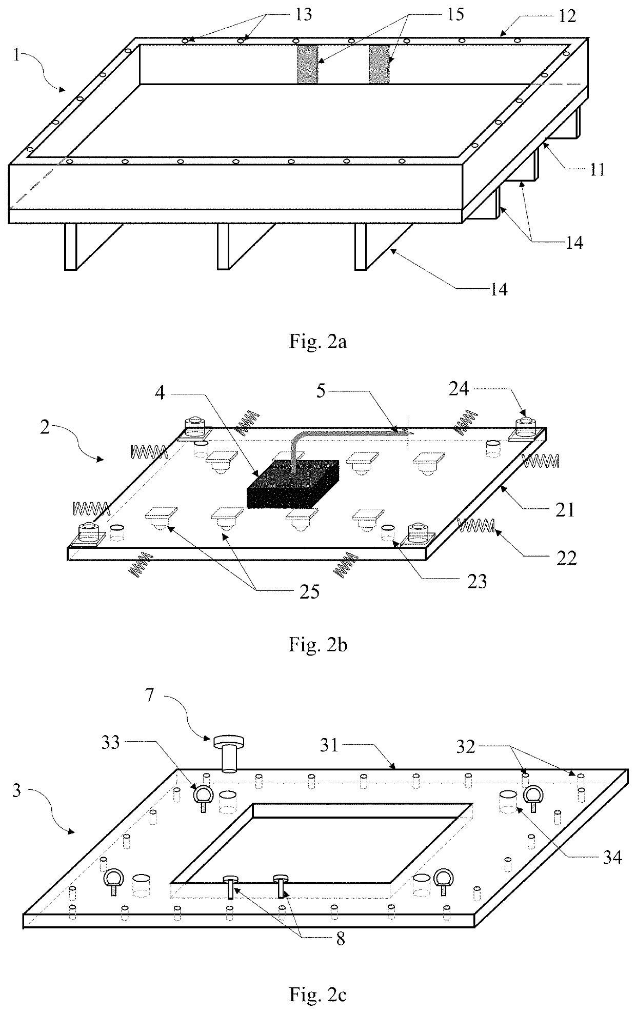
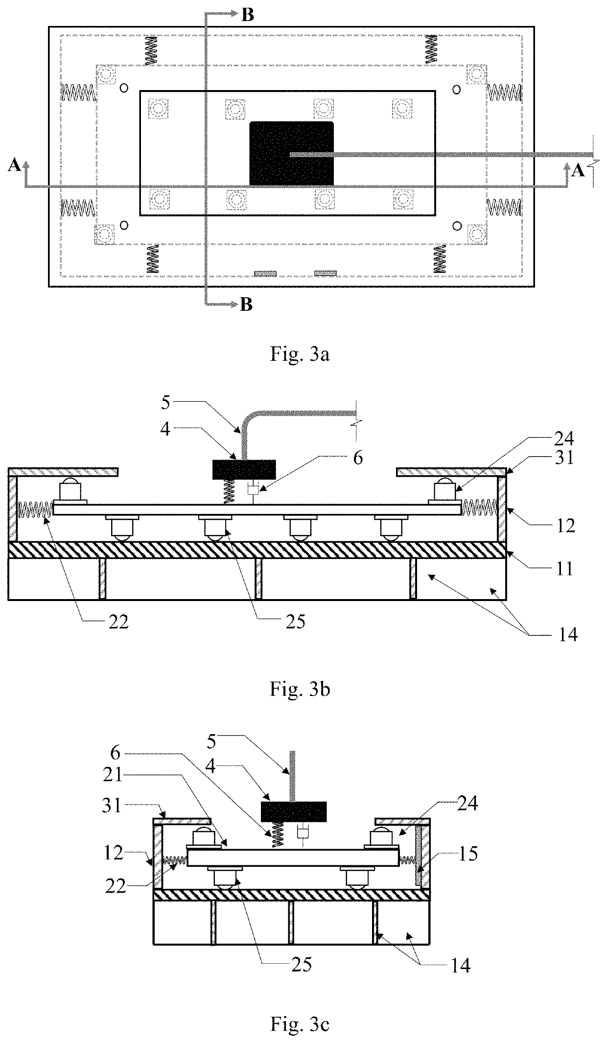
[0037]FIG. 1, FIGS. 2a-2c, and FIGS. 3a-3c show the free-sliding seabed mudmat foundation, which is mainly comprised of a base foundation 1, an upper foundation 2, and a cover plate 3. The base foundation 1 comprises a base plate 11, a plurality of lateral baffles 12 and a plurality of skirts 14. The base plate 11 sits on the seabed to support the dead weights of the free-sliding seabed mudmat foundation and the subsea infrastructure 4. The skirts 14 are symmetrically attached to the bottom of the base plate 11, which are inserted in the seabed soils to improve the horizontal anti-sliding resistance and vertical bearing capacity of the free-sliding seabed mudmat foundation. Hence the stability of the free-sliding seabed mudmat foundation is improved. The skirts 14 can also improve the rigidity of t...


PUM


Abstract

The present invention relates to a free-sliding seabed mudmat foundation, which belongs to the fields of offshore and ocean engineering. The mudmat comprises a base foundation, an upper foundation, and a cover plate. The base foundation sits on the seabed to support dead weights of the mudmat itself and the subsea production system fixed on the mudmat. The upper foundation, with a plurality of universal rolling ball bearing being attached to the bottom, can slide on the base foundation when it is subjected to a horizontal push force generated by the pipeline during operation. Therefore, the axial load on the pipeline during operation due to heating and pressurization is released and the buckling failure risk is then reduced. The mudmat disclosed has smaller size and lighter weight, which is beneficial in reducing fabrication costs and reducing requirements for cranes on the pipeline laying vessel.

Description

FIELD OF THE INVENTION[0001]The present invention relates to a free-sliding seabed mudmat foundation, which can be applied to the fields of offshore engineering and ocean engineering.BACKGROUND OF THE INVENTION[0002]Subsea mudmat foundations are used to support varied subsea infrastructures, such as manifolds, pipeline span protection devices, wellhead base structures, flow limiting valves, isolation valves, pipeline end terminations (PLETs), etc. The pipeline, connected to the madmat, expands axially due to heating and pressurization during operation, and hence a horizontal push force will act on the mudmat. In conventional design, the mudmat should resist the horizontal push force, i.e. the mudmat doesn't slide on the seabed surface by reacting against the horizontal push force. Therefore, the mudmat should be large enough to meet the requirements in anti-slide design.[0003]Generally, both the mudmats and pipelines are installed by a pipeline laying vessel. If the size of the mudm...

Claims


Application Information

Patent Timeline
Patent Type & Authority Patents(United States)
IPC IPC(8): E02D27/52E02D27/04E02D27/46E02D31/08
CPCE02D27/52E02D27/04E02D27/46E02D27/525E02D31/08E02D27/44F16L1/20E02D23/16
Inventor LIU, JUNHAN, CONGCONG
Owner DALIAN UNIV OF TECH
Learn More