Reconfiguration control device
a control device and reconfiguration technology, applied in the field of reconfiguration control devices, can solve the problems of power consumption, cost, and other factors, and achieve the effects of high reliability, high performance and low cos
- Summary
- Abstract
- Description
- Claims
- Application Information
AI Technical Summary
Benefits of technology
Problems solved by technology
Method used
Image

Examples
first embodiment
[0028]An example of an embodiment of the invention will be described with reference to FIGS. 1 to 5.
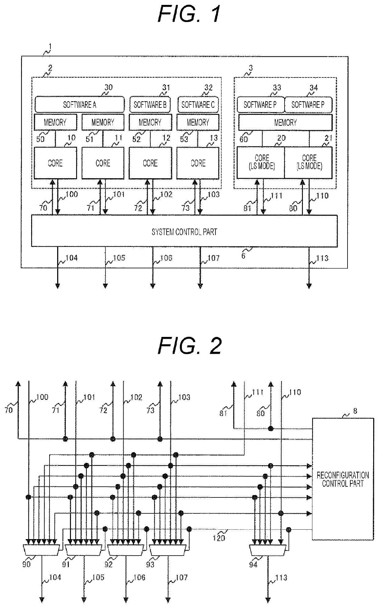
[0029]FIG. 1 illustrates an example of a reconfiguration control device of the invention.
[0030]In the reconfiguration control device illustrated in FIG. 1, four cores 10, 11, 12, and 13 are configured to be a multi-core. The core 10 is connected to a memory 50, and the software of the core 10 is arranged in the memory 50 and performs processing. Similarly, the core 11 is connected to a memory 51, the core 12 is connected to a memory 52, and the core 13 is connected to a memory 53, and each software is arranged in the memory and performs processing. In the example of FIG. 1, software A (30) is arranged in the memories 50 and 51, and multi-core operation is performed in the cores 10 and 11. On the other hand, the software B (31) is arranged only in the memory 52 and operates on the core 12, and similarly the software C (32) is arranged only in the memory 53 and operates on the core 13. ...
second embodiment
[0053]Next, an example of another embodiment of the invention will be described with reference to FIGS. 6 to 10.
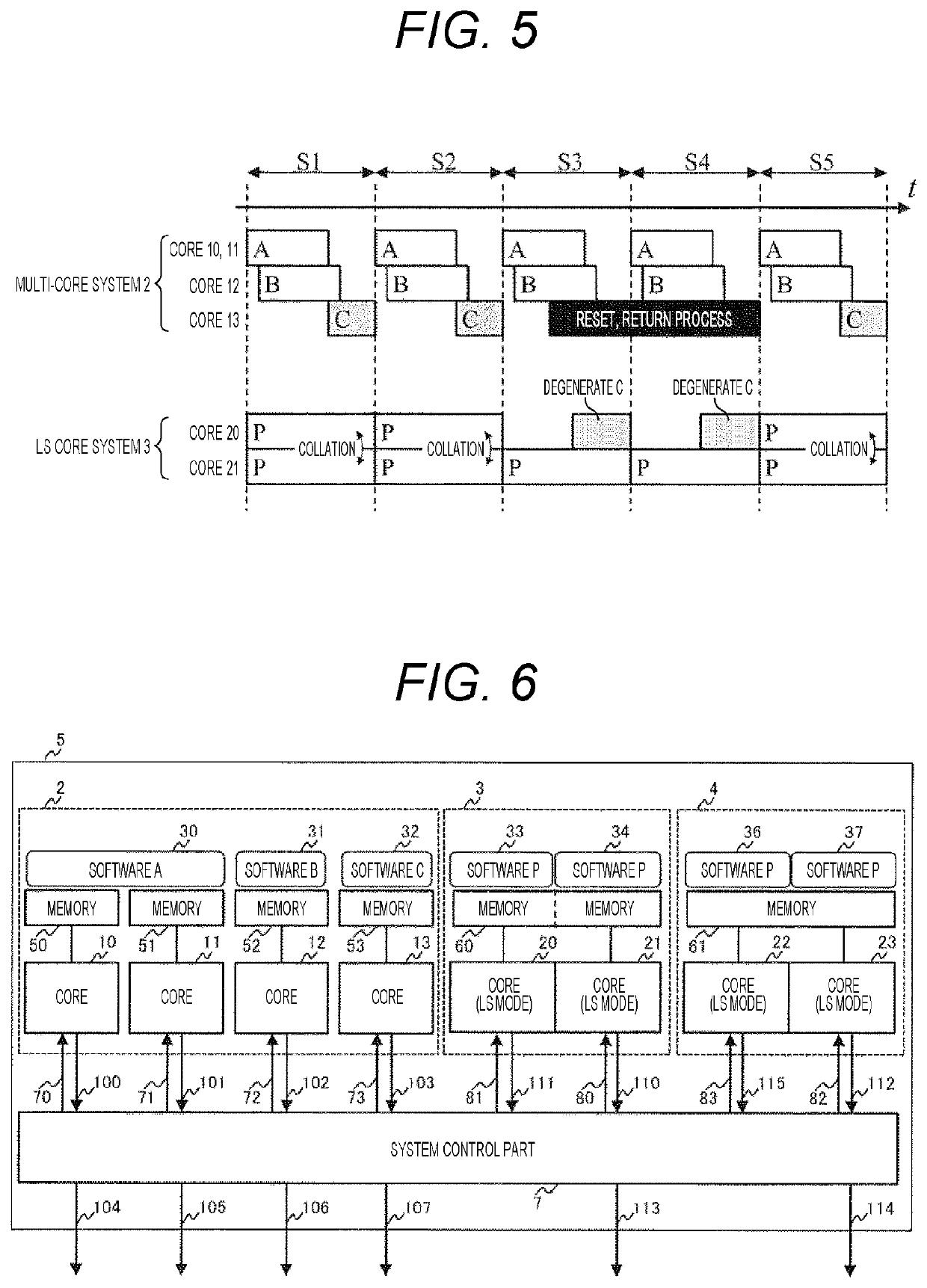
[0054]Compared to FIG. 1 of the first embodiment in the reconfiguration control device of the present invention, FIG. 6 is different in that one lockstep core system is added to form a dual lockstep core system configuration. In FIG. 6, a lockstep core system 4 including the cores 22 and 23, the memory 61, the software P (36), and the software P (37) is provided in addition to the lockstep core system 3 including the cores 20 and 21, the memory 60, the software P (33), and the software P (34). Similarly to the lockstep core system 3, in the lockstep core system 4, the cores 22 and 23 shares the memory 61, and the software P (36) operates on the core 22, the same software P (37) as the software P (36) operates on the core 23, and the collation is performed during operation to detect the occurrence of an error. Furthermore, compared to the system control part 6 described in ...
third embodiment
[0070]Next, an example of another embodiment of the invention will be described with reference to FIGS. 11 and 12.
[0071]FIG. 11 is different from FIG. 1 of the first embodiment in the reconfiguration control device of the invention in that the multi-core system and the lockstep core system are separated to be connected by a bus.
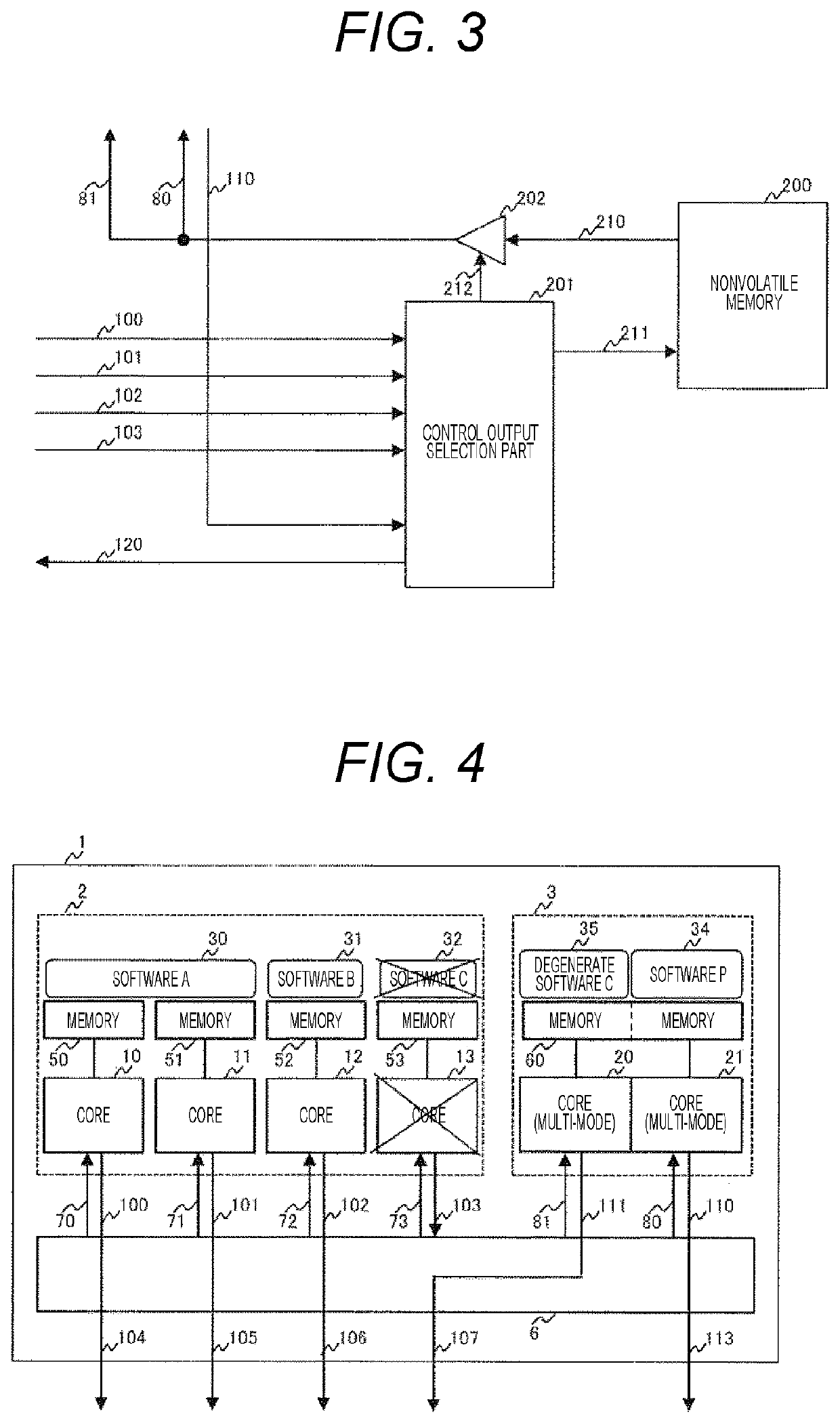
[0072]The system control part 16 in FIG. 11 corresponds to the multi-core system 2, the system control part 17 corresponds to the lockstep core system 3, the system control parts 16 and 17 are connected by the control bus 301 and the memory bus 302, and the nonvolatile memory 300 is connected to the memory bus 302. Similarly to the internal configuration of the system control part 6 described with reference to FIG. 2, the internal configuration of the system control parts 16 and 17 includes a multiplexer and a reconfiguration control part. FIG. 12 is an example illustrating a configuration of a case where the lockstep operation is switched to the multi-core o...
PUM
 Abstract
Description
Claims
Application Information
 - R&D
- Intellectual Property
- Life Sciences
- Materials
- Tech Scout
- Unparalleled Data Quality
- Higher Quality Content
- 60% Fewer Hallucinations
Browse by: Latest US Patents, China's latest patents, Technical Efficacy Thesaurus, Application Domain, Technology Topic, Popular Technical Reports.
© 2025 PatSnap. All rights reserved.Legal|Privacy policy|Modern Slavery Act Transparency Statement|Sitemap|About US| Contact US: help@patsnap.com