
Delay-encoded harmonic imaging with an ultrasound system

a delay-encoded, harmonic imaging technology, applied in the direction of instruments, measurement devices, complex mathematical operations, etc., can solve the problems of low snr when imaging deep regions, unsatisfactory resolution, and the general problem of ultrafast ultrasound imaging techniques

Active Publication Date: 2022-07-12
MAYO FOUND FOR MEDICAL EDUCATION & RES
View PDF19 Cites 0 Cited by
  • Summary
  • Abstract
  • Description
  • Claims
  • Application Information

AI Technical Summary

Benefits of technology

This patent describes a method for using ultrasound to create images of a subject. The method involves transmitting multiple ultrasound pulses and then processing the resulting data to create an image. A coding matrix is used to determine which pulses to apply a time delay to, resulting in a more precise image. The method also includes a memory to store the timing of the pulses and a controller to manage the transmission and reception process. The ultimate result is a more accurate and reliable way to use ultrasound for medical imaging.

Problems solved by technology

Because of these trade-offs, ultrafast ultrasound imaging techniques generally face several technical challenges.
One such challenge with ultrafast ultrasound imaging techniques is their unsatisfying resolution due to insufficient compounding angles to synthesize transmit focus.
Another such challenge with ultrafast ultrasound imaging techniques is their low SNR when imaging deep regions.
Still another challenge with ultrafast ultrasound imaging techniques is the degraded image quality from clutter noises due to secondary lobes, phase aberration, and reverberation caused by tissue inhomogeneities.
One disadvantage of MW imaging, however, is that it suffers strong clutter noises, such as reverberation in B-mode images, due to the long transmission pulses.
These clutter noises result in degraded images.
However, one limitation of HI is its low SNR and penetration depth caused by the low harmonic-to-fundamental ratio and frequency dependent attenuation (i.e., high frequency harmonics are more attenuated compared to fundamental signals).
However, the challenge with such a combination is that the ±1 coding factors in Hadamard matrix cannot be used to encode the 2nd harmonic as in MW imaging.

Method used


Image

  • Delay-encoded harmonic imaging with an ultrasound system
  • Delay-encoded harmonic imaging with an ultrasound system
  • Delay-encoded harmonic imaging with an ultrasound system

Examples


Embodiment Construction

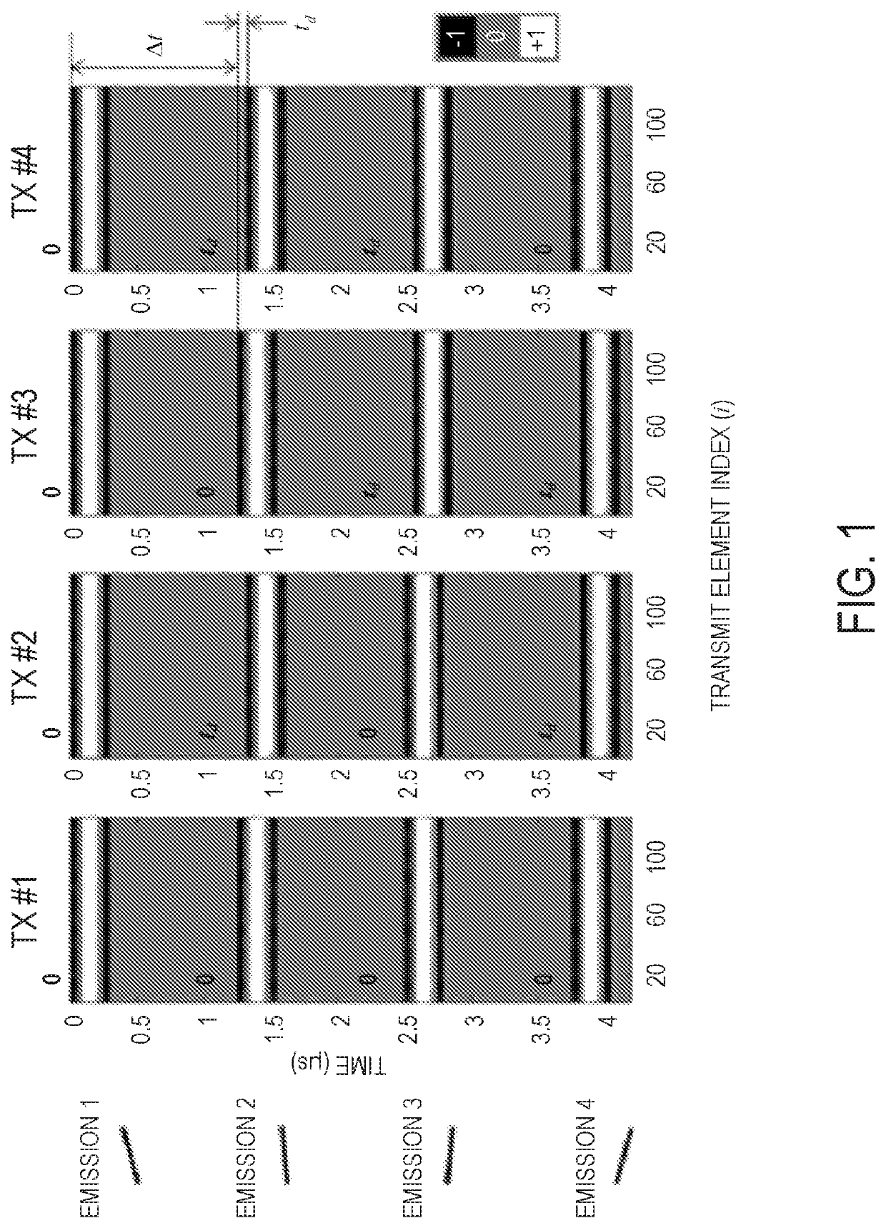
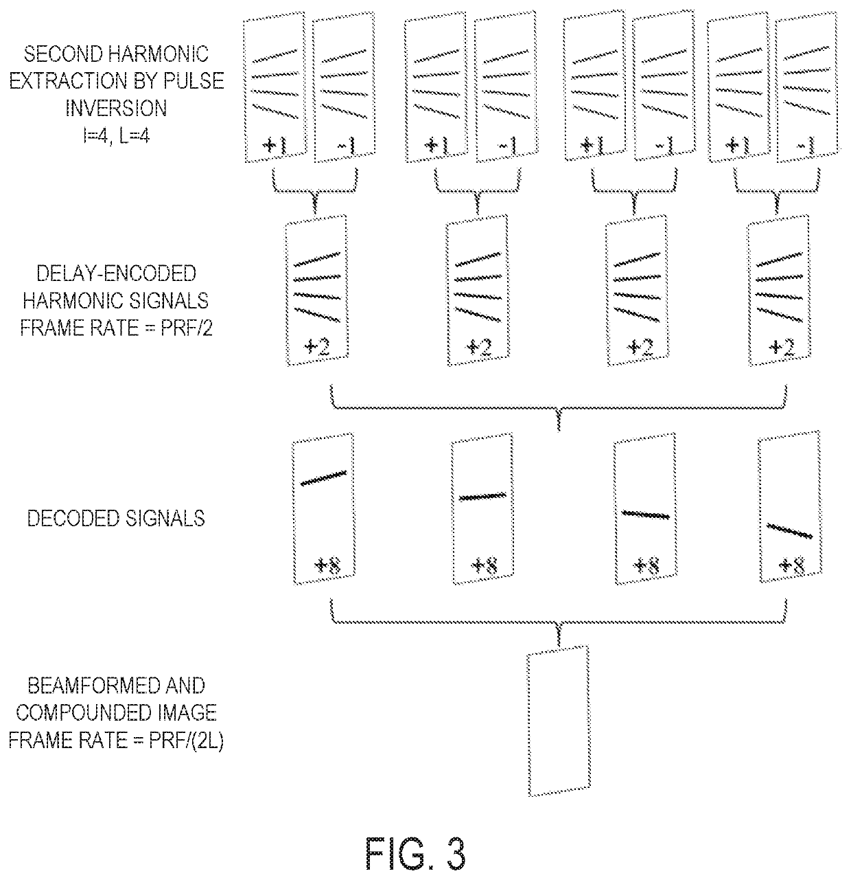
[0021]Described here are systems and methods for ultrasound imaging using a delay-encoded harmonic imaging (“DE-HI”) technique, in which a multiplane wave (“MW”) sequence is coded using temporal delays between emissions within a single transmission event. This coded scheme allows for harmonic imaging to be implemented. The temporal time delay codes are applied temporally to multiple different plane waves within a single transmission event, rather than spatially across different transmitting elements. The received radio frequency (“RF”) signals undergo a decoding process in the frequency domain to recover the signals, as they would be obtained from standard single plane wave emissions, for subsequent compounding. As one specific example, a one-quarter period time delay can be used to encode the 2nd harmonic signals from each angle emission during a single MW transmission event, rather than inverting the polarity of the pulses as in conventional MW imaging. However, other time delays ...


PUM


Abstract

Systems and methods for ultrasound imaging using a delay-encoded harmonic imaging (“DE-HI”) technique is provided. An ultrasound pulse sequence is coded using temporal delays between ultrasound emissions within a single transmission event. This coded scheme allows for harmonic imaging to be implemented. The temporal time delay-codes are applied temporally to multiple different ultrasound emissions within a single transmission event, rather than spatially across different transmitting elements. The received radio frequency (“RF”) signals undergo a decoding process in the frequency domain to recover the signals, as they would be obtained from standard single emissions, for subsequent compounding. As one specific example, a one-quarter period time delay can be used to encode second harmonic signals from each angle emission during a single multiplane wave (“MW”) transmission event, rather than inverting the polarity of the pulses as in conventional MW imaging.

Description

CROSS-REFERENCE TO RELATED APPLICATIONS[0001]This application is a 371 U.S. National Phase Entry application of PCT / US17 / 57304, filed on Oct. 19, 2017, which claims the benefit of U.S. Provisional Patent Application Ser. No. 62 / 410,998, filed on Oct. 21, 2016, and entitled “DELAY-ENCODED HARMONIC IMAGING WITH AN ULTRASOUND SYSTEM,” each of which is herein incorporated by reference in its entirety.BACKGROUND OF THE DISCLOSURE[0002]The development of ultrafast ultrasound imaging techniques offers great opportunities to new imaging technologies, such as shear wave elastography, ultrafast Doppler imaging, and diverging wave compounding. In compounded ultrafast imaging, high frame rate B-mode images are acquired by coherently combining several plane (or diverging) wave emissions with different tilted angles. The frame rate is significantly improved compared to conventional line-by-line focused B-mode imaging; however, the high frame rate is usually achieved by sacrificing other quality m...

Claims


Application Information

Patent Timeline
Patent Type & Authority Patents(United States)
IPC IPC(8): G01S15/89G01S7/52G06F17/16
CPCG01S15/8963G01S7/52022G01S7/52028G01S7/52093G01S15/8977G06F17/16G01S7/5202G01S15/8959G01S15/8995G01S7/52038G01S7/52077G01S15/8915
Inventor GONG, PINGSONG, PENGFEICHEN, SHIGAO
Owner MAYO FOUND FOR MEDICAL EDUCATION & RES
Learn More