
Thermoelectric power generator and combustion apparatus

a technology of thermal energy generators and combustion apparatuses, which is applied in the direction of combustion types, domestic cooling apparatus, combustion using catalytic materials, etc., to achieve the effect of reducing the long-term operating costs of such facilities, reducing the cost of potable water production, and effective utilitarian valu

Active Publication Date: 2022-06-14
UNIV OF CENT FLORIDA RES FOUND INC +1
View PDF30 Cites 0 Cited by
  • Summary
  • Abstract
  • Description
  • Claims
  • Application Information

AI Technical Summary

Benefits of technology

The patent text discusses a device that uses a porous media burner / combustion apparatus powered by liquid logistic fuels, such as kerosene, to produce potable water. The use of this device can provide a cost-effective and efficient means of providing clean water in military or civilian habitations. Kerosene can also be used as a heat source for portable dwellings and to remove moisture from wet clothing. The device can also provide a cost-effective method of supplying heat for portable HVAC systems and recreational vehicles. Overall, the use of an efficient kerosene powered device can greatly reduce the long term operating costs of such facilities.

Problems solved by technology

Thus, thermoelectric generators and combustion apparatuses of an embodiment well-suited for long-to-medium duration usage in remote environments (environments that do not have access to convenient shipping / purchasing methods of rechargeable batteries) where there is a reliable propane supply or enough storage space to house a large amount of propane; and either the inability to pay for a bundle of batteries with the same energy capacity or the inability to obtain a bundle of batteries with the same energy capacity.

Method used


Image

  • Thermoelectric power generator and combustion apparatus
  • Thermoelectric power generator and combustion apparatus
  • Thermoelectric power generator and combustion apparatus

Examples


example 1

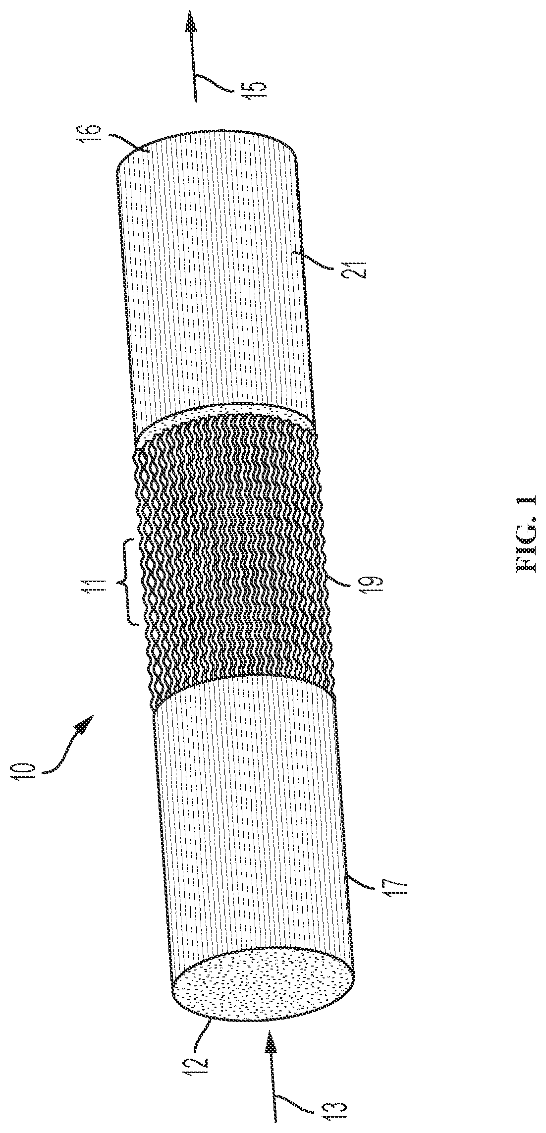
[0075]This Example describes the depositing of catalytic enhancement on the porous burner with the matrix stabilized porous medium 10. The catalytic enhancement is deposited on the surfaces of Al2O3 and / or SiC reticulated foams which are typically catalytically inert and are used as a section to contain the flame and facilitate the combustion. All of the powders of the compositions of interest for the coating are used to coat the porous burner using the dip coating technique. In brief, dip coating is a very simple slurry coating technique which refers to a) immersing a sample (in this case porous ceramic matrix) into a tank, containing a slurry with a coating material; b) allowing the sample to remain in the slurry for a predetermined optimal time; c) removing the sample from the tank, placing the sample in the vacuum furnace and allowing the sample with coating to dry at 50-60° C. and 10−2 Pa for 2-3 hours. Dip coating is fairly straightforward and is the preferable technique for t...

example 2

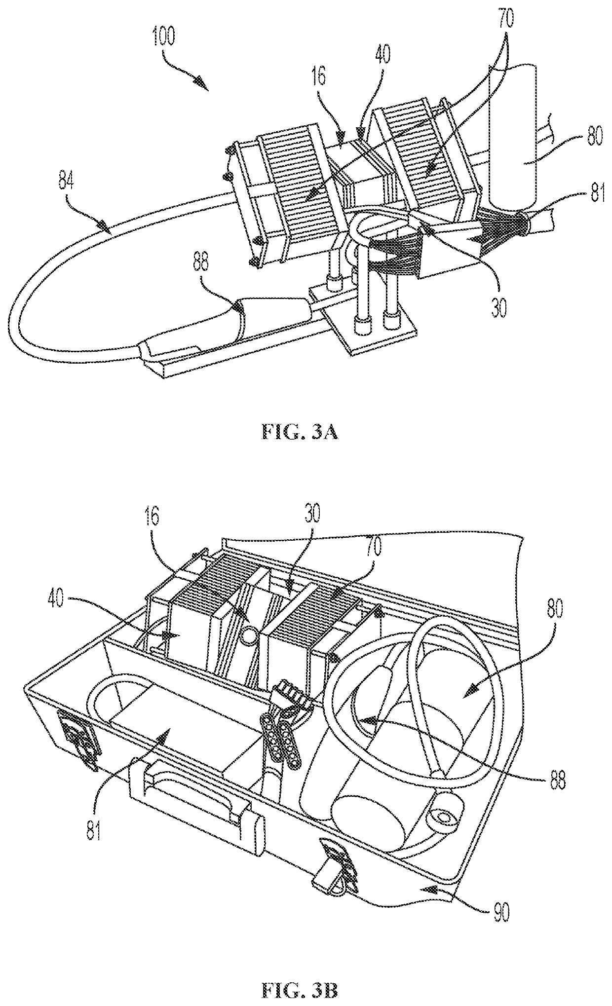
[0076]This Example describes the calculation of a theoretical power output of a thermoelectric power generator for powering small-scale electronic devices of an embodiment. By harvesting combustion heat from an ultra-efficient burner in a high-density manner using thermoelectric generators coupled with low-profile integrated fansink heat sinks, the thermoelectric power generator of an embodiment can provide an improved level of power density for portable-scale applications (i.e. powering a cell phone, small laptop, pump, fan, etc.) while maintaining an ample level of affordability.

[0077]The thermoelectric power generator's pertinent performance parameters are been listed in Table 1, below.

[0078]

TABLE 1Theoretical system performance parametersVolumetric flow1.41rate of fuel[L / min]Maximum Net17.3Power Output[W]Maximum Net74.4Power Density(tanks & unit)[W / ft3]Net Power21.7Density (wholesystem) [W / ft3]Specific1,020Power(tanks &unit)[mW / lbm]Specific785Power(wholesystem)[mW / lbm]Energy Cap...


PUM


Abstract

A small-scale thermoelectric power generator and combustion apparatus, components thereof, methods for making the same, and applications thereof. The thermoelectric power generator can include a burner including a matrix stabilized combustion chamber comprising a catalytically enhanced, porous flame containment portion. The combustion apparatus can include components connected in a loop configuration including a vaporization chamber; a mixing chamber connected to the vaporization chamber; a combustion chamber connected to the vaporization chamber; and a heat exchanger connected to the combustion chamber. The combustion chamber can include a porous combustion material which can include a unique catalytic material.

Description

RELATED APPLICATION DATA[0001]The present application claims priority to and the benefit of U.S. provisional patent application No. 61 / 950,891, filed on Mar. 11, 2014, the entire contents of which are hereby incorporated by reference.FIELD OF THE INVENTION[0002]The present disclosure is directed generally to thermoelectric generators (TEG) and combustion apparatuses, and more particularly, to thermoelectric generators and combustion apparatuses including combustion chambers with catalytically enhanced porous portions.BACKGROUND[0003]With the advancement of technology in both the developing and developed world, it is becoming more evident that the low lifetime, low energy density, and somewhat limited accessibility of traditional batteries limits the applications of portable electronic devices. Hydrocarbon fuels are readily available in most societies and have a much higher energy density than traditional batteries, thus making them a very attractive resource for man-portable power g...

Claims


Application Information

Patent Timeline
Patent Type & Authority Patents(United States)
IPC IPC(8): F23C13/08F01K13/00F02G1/043H01L35/26H01L35/32F23C7/00F23C9/00F23C6/00F23C1/00F01K19/00F25D23/12F22D1/00H10N10/857H10N10/17
CPCH01L35/26F01K13/006F02G1/043F23C13/08H01L35/32F01K19/00F02G2254/05F02G2254/10F02G2254/11F02G2254/70F22D1/003F23C1/00F23C6/00F23C7/00F23C9/00F23C2900/13001F23C2900/13002F23C2900/99011F23M2900/13003F24H2240/127F25D23/12G06F2207/4913H10N10/857H10N10/17
Inventor ORLOVSKAYA, NINATERRACCIANO, ANTHONYDASGUPTA, ARINDAM
Owner UNIV OF CENT FLORIDA RES FOUND INC
Learn More