
Sliding bearing, bearing apparatus, and image forming apparatus

a technology of sliding bearings and bearings, applied in the direction of bearing units, bearing cooling, bearing units rigid support, etc., can solve the problems of complex structure of ball bearings and high cost, and achieve the effects of suppressing the increase of shaft temperature, reducing friction, and improving low friction performan

Active Publication Date: 2022-05-31
NTN CORP
View PDF35 Cites 0 Cited by
  • Summary
  • Abstract
  • Description
  • Claims
  • Application Information

AI Technical Summary

Benefits of technology

The solution effectively suppresses shaft temperature increases, enhances continuous operation, and simplifies manufacturing, while maintaining low friction and wear resistance, thus improving the performance and reliability of image forming apparatuses.

Problems solved by technology

However, the structure of the ball bearing is complex and high in cost.

Method used


Image

  • Sliding bearing, bearing apparatus, and image forming apparatus
  • Sliding bearing, bearing apparatus, and image forming apparatus
  • Sliding bearing, bearing apparatus, and image forming apparatus

Examples


example 1

[0123]A pellet is formed by compounding 80 vol % of the injection-moldable ultrahigh molecular weight PE resin powder (weight average molecular weight: 250,000 to 600,000) as a base resin, 15 vol % of the PTFE resin as an additive, and 5 vol % of a calcium carbonated whisker, which is an acicular inorganic filler having the Mohs hardness of 3 or less, mixing and melt kneading the powder. And then, a test piece for a friction and wear test and a test piece for a physical property measuring test are molded by injection-molding the pellet.

Friction and Wear Test

[0124]The test is performed by using a radial type friction and wear test. A cylindrical test piece of ϕ12×ϕ8×t10 mm is adopted as the friction and wear test piece. Two kinds of the rotation shafts formed of SUS 303 and POM resin (no filler) respectively are adopted as the mating shaft. The test condition using the SUS shaft is set to surface pressure of 0.7 MPa, speed of 0.15 m / s, rotation time of 30 minutes, and test starting t...

example 2 to example 5

[0127]A test piece of each Example is molded similar to the test piece of Example 1, except that the base resin, which is the same as Example 1, the additive and the inorganic filler shown in Table 1 are compounded at each compounding ratio shown in Table 1. The test similar to Example 1 is performed to each test piece.

example 6

[0140]The sliding bearing adopts the resin composition of Example 1. This sliding bearing is assembled to the housing of Comparative example 7 in which the grooves for heat dissipation are formed so as to obtain a bearing apparatus.


PUM

PropertyMeasurementUnit
particle diameteraaaaaaaaaa
Rockwell hardnessaaaaaaaaaa

Abstract

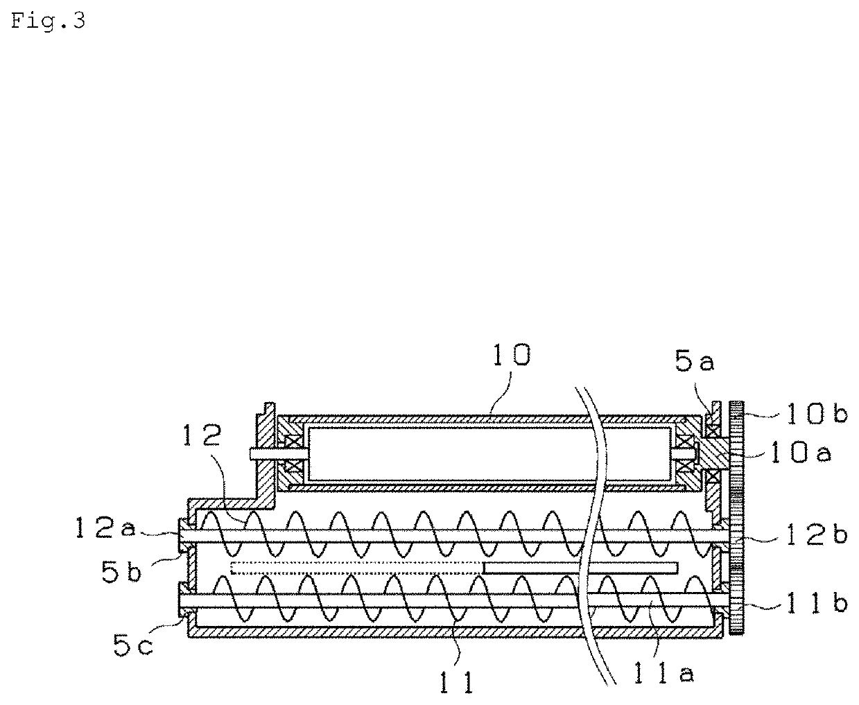
To provide a non-oil-impregnated sliding bearing having superior low friction capable of suppressing an increase of a shaft temperature in a continuous use, and a bearing apparatus and an image forming apparatus provided with the sliding bearing. Sliding bearings 5a to 5c support rotation shafts on cylinder inner surface in a rotatable manner. Each of the sliding bearings 5a to 5c is formed of a molded member of a non-oil-impregnated resin composition that does not contain oil. The resin composition contains an injection-moldable ultrahigh molecular weight polyethylene resin as a base resin, a polytetrafluoroethylene resin as an additive, and an acicular inorganic filler having Mohs hardness of 3 or less. The resin composition contains 65 vol % or more of the ultrahigh molecular weight polyethylene resin, 5-25 vol % of the polytetrafluoroethylene resin, and 1-20 vol % of the acicular inorganic filler, based on the whole of the resin composition.

Description

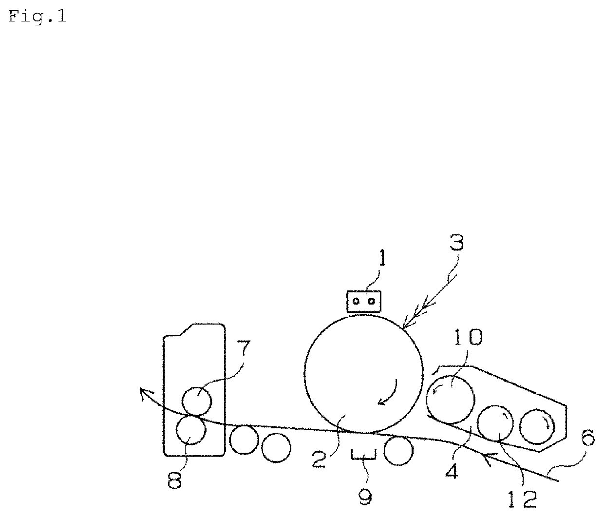
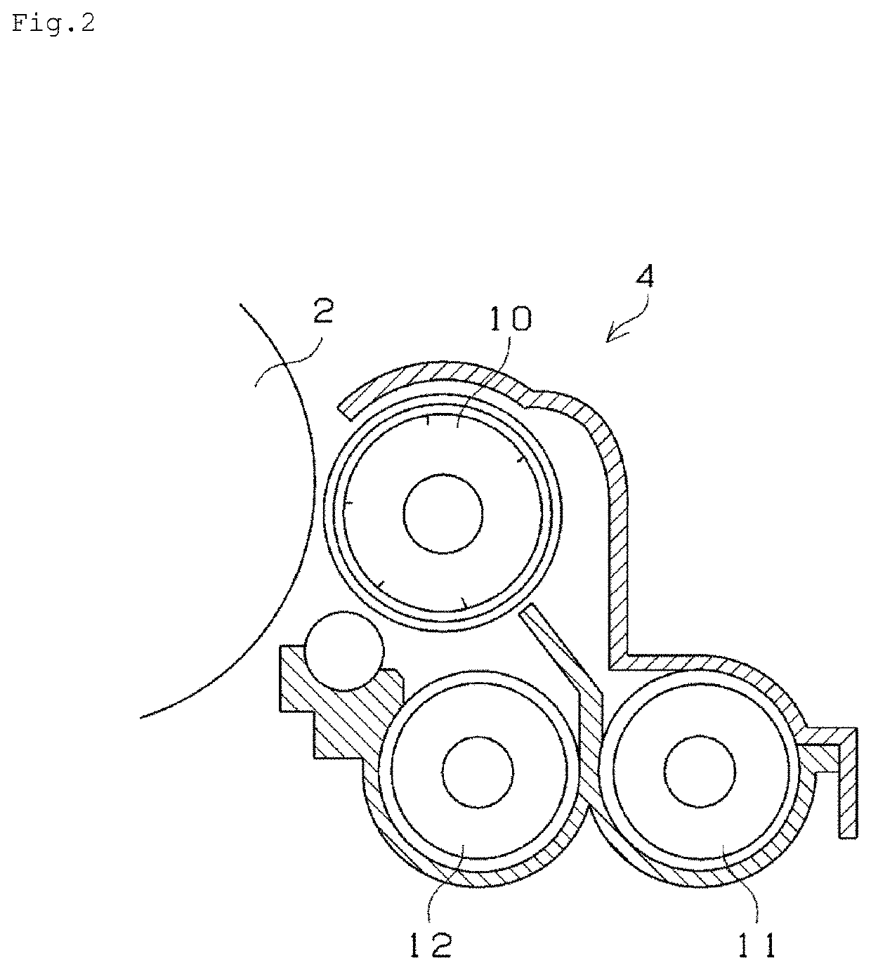
TECHNICAL FIELD[0001]The present invention relates to a sliding bearing, and, in particular, to a sliding bearing used to support various types of rollers and shafts in a developer unit, a photoreceptor unit, a transfer unit, a paper ejector unit, a paper feeder unit, or the like, of an image forming apparatus such as a copier, a multifunction machine, a printer (a laser printer, an inkjet printer, or the like), and a fax machine. The present invention also relates to a bearing apparatus and an image forming apparatus provided with the sliding bearing.BACKGROUND ART[0002]An image forming apparatus such as a copier and a printer is provided with a rotatable developer roller that develops a latent electrostatic image formed on a photoreceptor drum, and a supply roller arranged to contact the developer roller so as to supply toner. The image forming apparatus transfers the toner to the latent electrostatic image on the photoreceptor drum using the developer roller and the supply roller...

Claims


Application Information

Patent Timeline
Patent Type & Authority Patents(United States)
IPC IPC(8): F16C33/20F16C17/02F16C17/24
CPCF16C33/201F16C17/02F16C17/243F16C2202/04F16C2208/02F16C2208/32F16C2208/78F16C2324/16C08L23/06C08L27/18F16C33/20G03G15/00G03G15/08F16C35/02F16C37/00F16C2208/22
Inventor MUNEDA, NORIKAZUHIROSE, KAZUO
Owner NTN CORP
Learn More