Engine and rotatable proprotor configurations for a tiltrotor aircraft

a technology of proprotors and tiltrotors, which is applied in the direction of vertical landing/take-off aircrafts, power plant construction, power plant construction, etc., can solve the problems of limiting the ability to incorporate wing extensions outboard of the engine, limiting the diameter of the propeller, and difficult storage and maintenance of the aircraft, so as to reduce the stress on the wing structure, increase the lift, and maximize the lift

Active Publication Date: 2022-05-24
TEXTRON INNOVATIONS
View PDF29 Cites 0 Cited by
  • Summary
  • Abstract
  • Description
  • Claims
  • Application Information

AI Technical Summary

Benefits of technology

[0005]In accordance with the present invention, the engine is therefore fixed below the wing, whereas the pylon and proprotor assembly are located above the wing, providing flexibility for storage while maximizing the lift generated by allowing more air to pass over the surface of the wing, while simultaneously providing more bottom surface of the wing to allow for lift. Additionally, the configuration shown takes the engine out of the wing central axis, thereby reducing the stress on the wing structure. Additionally, by mounting the proprotor pylon and engine above and below the wing, respectively, wing extensions may be added on the outboard side of the propulsion system, thereby further increasing the lift and reducing fuel consumption to allow for longer flight duration. The wing extensions may be removable or foldable to aid in storage and / or transportation of the tiltrotor aircraft.
[0006]To facilitate the separate placement of the fixed engine and rotatable proprotor, one or more gearboxes may be placed in the driveline from the engine output shaft to the proprotor input. In this manner, the direction of the drive shafts may be altered to facilitate flexibility in the placement of the engine and proprotor. Additionally, an interconnect drive system may be included, such that an interconnect drive shaft connects the engine on one side of the aircraft to the proprotor on the other side of the aircraft in the event of a loss of power by one engine. This interconnect drive system may include a gearbox that facilitates the change in direction of the engine output drive to accommodate the separation of the engine and proprotor in various configurations.

Problems solved by technology

While the V-22 is an extremely successful design for a multi-use aircraft, the mechanical requirements of the engine, proprotor, and wing make storage and maintenance of the aircraft difficult.
While an improvement to locate the engine and proprotor at the end of the wing distal from the fuselage, this configuration limits the ability to incorporate wing extensions outboard of the engine.
Another drawback of the '678 design is that the inboard location of the proprotor limits the diameter of the propeller, and the outboard location of the engine limits the ability to break down the wing for storage.

Method used


Image

  • Engine and rotatable proprotor configurations for a tiltrotor aircraft
  • Engine and rotatable proprotor configurations for a tiltrotor aircraft
  • Engine and rotatable proprotor configurations for a tiltrotor aircraft

Examples


Embodiment Construction

[0014]The disclosure below includes several illustrative embodiments of the system of the present invention. In the interest of clarity, all of the features of the systems are not described in detail, but would be apparent to one of ordinary skill in the art as being a requirement to build a fully functioning design implementing the novel inventions disclosed. Numerous implementation-specific decisions would necessarily be made during the design and construction of an aircraft that meets the goals of the builder. I should be apparent that while any development effort might be complex and time-consuming, it would be routine for one or more of ordinary skill in the art.

[0015]The specific special relationships of various components are not described in detail, as those represent design variations well within the level of skill in the art.

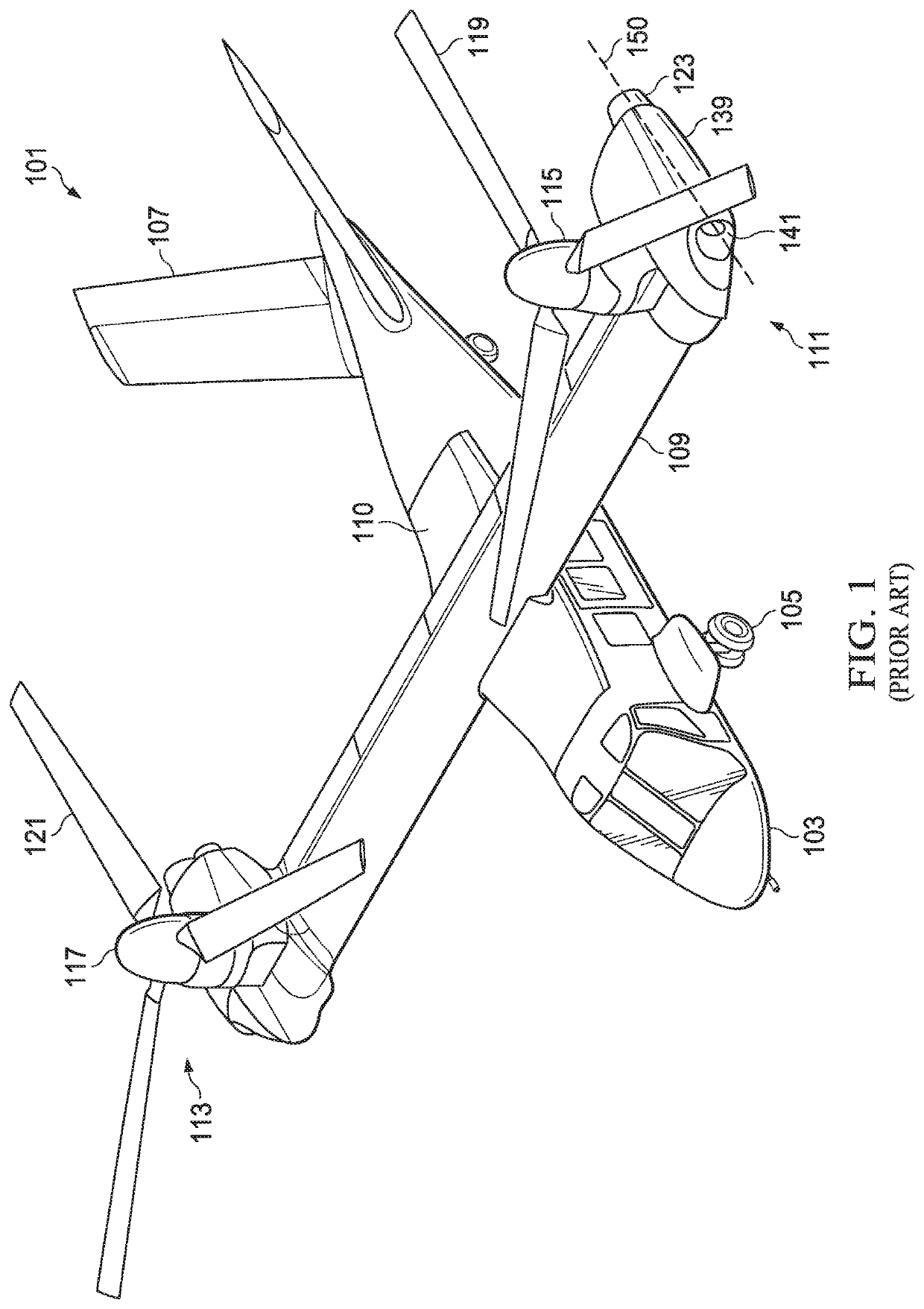
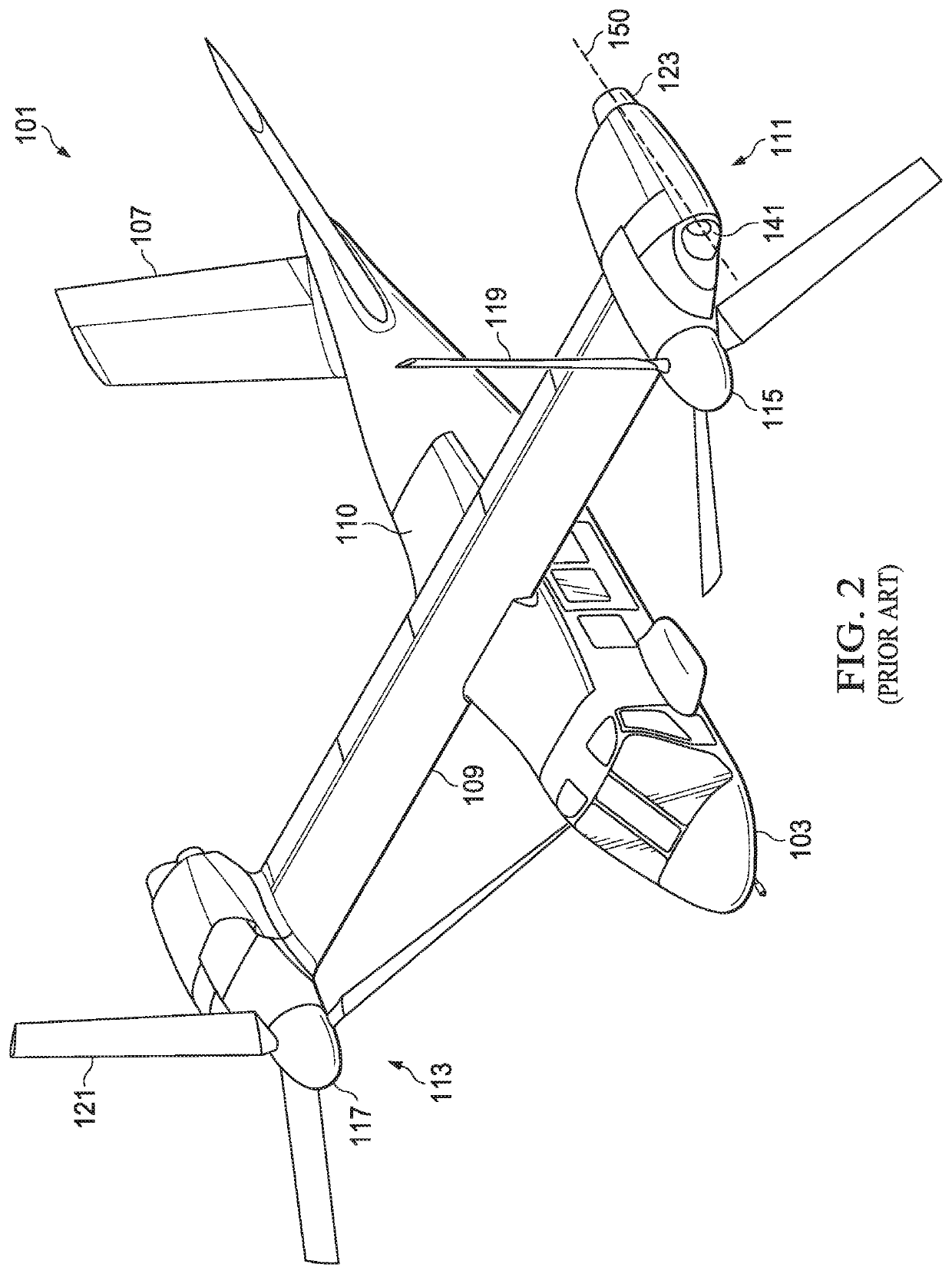
[0016]FIGS. 1 and 2 show a tiltrotor aircraft in accordance with a prior art fixed-engine design, but is nevertheless useful in describing the improve...


PUM


Abstract

A tiltrotor aircraft includes a propulsion system with a fixed engine and a rotatable proprotor. The engine is located below the wing of the tiltrotor aircraft, and the rotatable proprotor assembly is mounted on the top surface of the wing. The engine and proprotor assembly are connected via a series of one or more gearboxes that route the engine output from the engine to the proprotor.

Description

BACKGROUND OF THE INVENTION1. Field of the Invention[0001]This invention relates to engine and proprotor configurations for tiltrotor aircraft.2. Background of the Invention[0002]The present invention relates to wing-mounted engines for aircraft. In a typical configuration, to maximize efficiency, the engine and proprotor are configured linearly, whereby the engine has a straight shaft that drives the rotor or propeller. More recently, some aircraft have been developed, such as the V-22 Osprey by Bell Helicopter Textron Inc., that features an engine and proprotor that may be rotated 90° so that the aircraft is capable of vertical take-off and landing (VTOL).[0003]While the V-22 is an extremely successful design for a multi-use aircraft, the mechanical requirements of the engine, proprotor, and wing make storage and maintenance of the aircraft difficult. One improvement to the V-22 design includes a fixed engine with a rotating proprotor as shown in U.S. patent application Ser. No. 1...

Claims


Application Information

Patent Timeline
Patent Type & Authority Patents(United States)
IPC IPC(8): B64C29/00B64C3/56B64D27/26B64D35/08
CPCB64C29/0033B64C3/56B64D27/26B64D35/08
Inventor GILLILAND, COLTONWILLIAMS, JEFFREYRINEHART, MICHAEL E.KOOIMAN, JAMESPRZYBYLA, MARKSMITH, CLEGGOLSON, ERIC STEPHENDECKER, GEORGE RYANBOCKMILLER, DAVID RUSSELL
Owner TEXTRON INNOVATIONS
Why Eureka
Try Eureka