Audio signal output device, audio system, and audio signal output method
a technology of audio signal and output method, applied in the direction of speech analysis, instruments, electrical equipment, etc., can solve the problem of not being able to identify channels, and achieve the effect of reliable identification
- Summary
- Abstract
- Description
- Claims
- Application Information
AI Technical Summary
Benefits of technology
Problems solved by technology
Method used
Image
Examples
modified example 1
[0096]An output signal output from the PC 1 and an AV receiver 2A of Modified Example 1 will be described with reference to FIGS. 10 and 11. FIG. 10 is an explanatory diagram illustrating one example of the output signal. In FIG. 10, the horizontal axis of the channel represents samples (time) and the vertical axis represents bits (volume). FIG. 11 is a block diagram illustrating the main configuration of AV receiver 2A. Components that are the same as those of the AV receiver 2 described above have been assigned the same reference symbols, and their descriptions have been omitted.
[0097]For example, the PC 1 acquires audio signals of two channels (L channel and R channel) and outputs the audio signal of one (for example, the L channel) and a signal processing parameter MD of said audio signal in one channel. The signal processing parameters MD in this example is, for example, information specifying the type of effector to be applied to the audio signal, and a parameter for the effec...
modified example 2
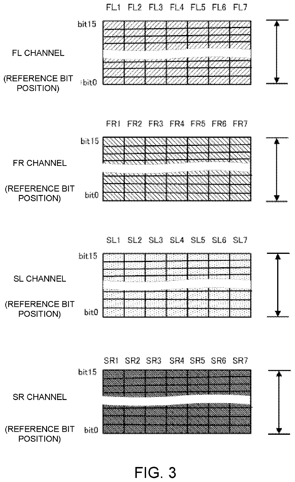
[0110]An output signal output from the PC 1 and AV receiver 2Aa of Modified Example 2 will be described with reference to FIGS. 12, 13, and 14. FIG. 12 is an explanatory diagram illustrating the output signal of an La channel and the output signal of an Ra channel. FIG. 13 is a block diagram illustrating the main configuration of AV receiver 2Aa. FIG. 14 is an explanatory diagram illustrating another example of an output signal of the La channel according to Modified Example 2 and an output signal of the Ra channel according to Modified Example 2. In FIGS. 12 and 14, the horizontal axis of each channel represents samples (time) and the vertical axis represents bits (volume). The PC 1 predefines the reference bit position for each audio signal of the four channels.
[0111]The audio signal processing unit 17 adds a signal processing parameter of each of the audio signals in a different position than a reference bit position of each of the audio signals. For example, before downmixing th...
modified example 3
[0123]An output signal output by the PC 1 and an AV receiver 2B of Modified Example 3 will be described with reference to FIGS. 15 and 16. FIG. 15 is an explanatory diagram illustrating one example of the output signal. FIG. 16 is a block diagram illustrating the main configuration of the AV receiver 2B.
[0124]In FIG. 15, the horizontal axis represents samples (time) and the vertical axis represents bits (volume). Components that are the same as those of the AV receiver 2 described above have been assigned the same reference symbols, and their descriptions have been omitted. In addition, for the sake of convenience, this example will be described based on the assumption that the number of quantization bits of the audio signal of each of the four channels is 8 bits and that the number of bits of the expansion region is 4 bits. Further, in this example, an example of downmixing from four channels into one channel will be described.
[0125]In this example, as shown in FIG. 15, the PC 1 ou...
PUM
 Abstract
Description
Claims
Application Information
 - R&D
- Intellectual Property
- Life Sciences
- Materials
- Tech Scout
- Unparalleled Data Quality
- Higher Quality Content
- 60% Fewer Hallucinations
Browse by: Latest US Patents, China's latest patents, Technical Efficacy Thesaurus, Application Domain, Technology Topic, Popular Technical Reports.
© 2025 PatSnap. All rights reserved.Legal|Privacy policy|Modern Slavery Act Transparency Statement|Sitemap|About US| Contact US: help@patsnap.com


