Tactile display having a magnetically bistable axially symmetrical linear actuator having a pole contour and switching matrix, and optical-tactile seeing aid having same

a linear actuator and axially symmetrical technology, applied in the field of magnetically bistable axially symmetrical linear actuators, can solve the problems of additional mechanical force deflection, no chance of automatic travel map machines with graphical route representation, and expensive ceramic actuators, etc., to achieve simple and cost-effective arrangement

Active Publication Date: 2022-04-05
GREINER LUITPOLD
View PDF5 Cites 0 Cited by
  • Summary
  • Abstract
  • Description
  • Claims
  • Application Information

AI Technical Summary

Benefits of technology

This patent aims to create an electromagnetic actuator for touch displays, such as braille displays and graphical surface displays. The actuator should be simple and inexpensive, with minimal thickness and resistance to dirt particles. The actuator should also be able to be used as an input unit without additional sensors or switches. Additionally, the patent aims to offer a device that can serve as a substitute for blind individuals and offer a simulation of a normal human facial on a tactile surface.

Problems solved by technology

The very expensive ceramic actuators, which as a rule operate as bending elements, require additional mechanical force deflections in order to realize a pin movement that runs perpendicular to the scanning surface at all.
The mechanical, electrical and economic disadvantages of the established piezo-modules also lead to the fact that, up to now, there is no “barrier-free” in the entire self-service area.
There may be no chance of automatic travel map machines with graphical route representation, automatic drinks machines or money / bank machines: the blind has no chance, these devices can be used discretely because, as a rule, no tactile output medium suitable for him is installed.
In conjunction with the required minimum forces (for example: 0.3N) for a reliable scanning operation by the feeling finger, small pin spacings are a fundamental problem, in the case of all axial actuator types in the vicinity of the tactile pin, a sufficient amount of functional material—in this case, for example, in the case of the magnetic actuator, in particular, a coil having a high number of wire windings—must be attached.
The simple alignment of all axial actuators of the tactile display in a plane (parallel to the plane of the touch pins) is therefore not possible for spatial reasons.
Of course, the problem of close screening also applies to the usually electrical actuation of the actuators.
In the case of piezo solutions, this results in a considerable overall height by, for example, complicated stacking techniques of a plurality of circuit boards, which leads to this, in particular for mobile applications, the piezoelectric technology is not least attractive—not least because of safety aspects in connection with the required high voltage (>100V) for controlling the actual bending elements.
In particular in each piezo solution it is disadvantageous that at least one stable pin position (“top” or “bottom”) can only be implemented by permanent electrical control.
DE 103 49 100 A1 likewise offers a piezo-surface solution, but the use of additional mechanical elements (toggle lever transmission) again the basic difficulty of ensuring a clear, clearly tactile “top” or “bottom” state of the pin.
DE 10 201 0 005 933 a1 likewise shows this problem: here, in addition to the use of a wedge gear in the resetting of the pins, it is even familiar to the force of gravity, which is subject to problems with regard to the correctness of the data display before the background of mobile applications.
The assembly of the overall display is complicated and results in a construction height of the device which is not acceptable, for example, for mobile applications.
For a compact—perhaps even mobile—tactile surface display device, the presented solution is likewise not suitable.
However, the “top” position, which is important for tactile applications, is here the least stable (lowest force of the system) the system immediately falls into the “down position” and, above all, a reliable representation of the data in the “off” state of the display is no longer possible.
However, these springs prevent the system from rapid response to control signals (opposite direction), weaken the above-holding force and additionally complicate the construction.
In order to treat the problem of forces, soft magnetic flux conducting devices are also required, as a result of which the actuator is neither compact nor inexpensive to produce.
However, the time response of these configurations does not satisfy the claims of rapid addressing.
As far as nowadays, there is virtually no “barrier-free”, for example, in the entire self-service area, there may be no chance to use these devices discretely because, as a rule, no reading unit suitable for him is installed.
The main source of interference is, however, contamination which originates solely from the nature of the tactile operation during reading or during the input: fat, skin particles, hair and sweat are introduced directly through the human being using the display.
Dust, moisture and provided wetting of the display with liquid additionally cause the service to be brought about earlier or later.
The disadvantage here is that the elevation of the feeler pins is less pronounced with respect to the display plane, that is to say reading of the tactile information is thus more cumbersome and less reliable.
In addition, it makes the structure of the unit more complicated and to think to a simple deconstruction of the individual pin—in the ideal case by the visually impaired end user himself—, even in the case of the embodiment shown.
It is disadvantageous here that even in the event of a malfunction of only a single pin, the entire pin unit has to be removed, because the pins themselves are incorporated in their unit so that they cannot be removed, that is to say they are not easily dismantled by the end user itself, and the purchase of the reserve pin unit naturally causes additional costs.
As a result, it is also clear that considerable expenditure for the mechanical precision (tolerance problem) of the two complex parts will be necessary.
For completely flashed people, this type of device does not, of course, represent any help.
Apart from the very limited lateral resolution of this method, this “see with the skin” is associated with a considerable, annual training effort.
The reliability of the method (for example the problem of electrical charges at high air humidity) is also doubtful.
No real image of the 3-dimensional real environment is available because of the lack of imaging lens elements.
Despite the use of a camera / scanner, a continuous tactile representation of an image of the environment that is closed without gaps is thus not possible.
Exactly here, the greatest disadvantage of the TIM is: the complicated control of zoom and section requires a large number of additional function keys, which have to be operated in a quasi-temporally parallel manner with the actual tactile “visual process”.
There are no tactile devices which are indispensable in the case of an auxiliary means for completely flashed people.

Method used


Image

  • Tactile display having a magnetically bistable axially symmetrical linear actuator having a pole contour and switching matrix, and optical-tactile seeing aid having same
  • Tactile display having a magnetically bistable axially symmetrical linear actuator having a pole contour and switching matrix, and optical-tactile seeing aid having same
  • Tactile display having a magnetically bistable axially symmetrical linear actuator having a pole contour and switching matrix, and optical-tactile seeing aid having same

Examples


Embodiment Construction

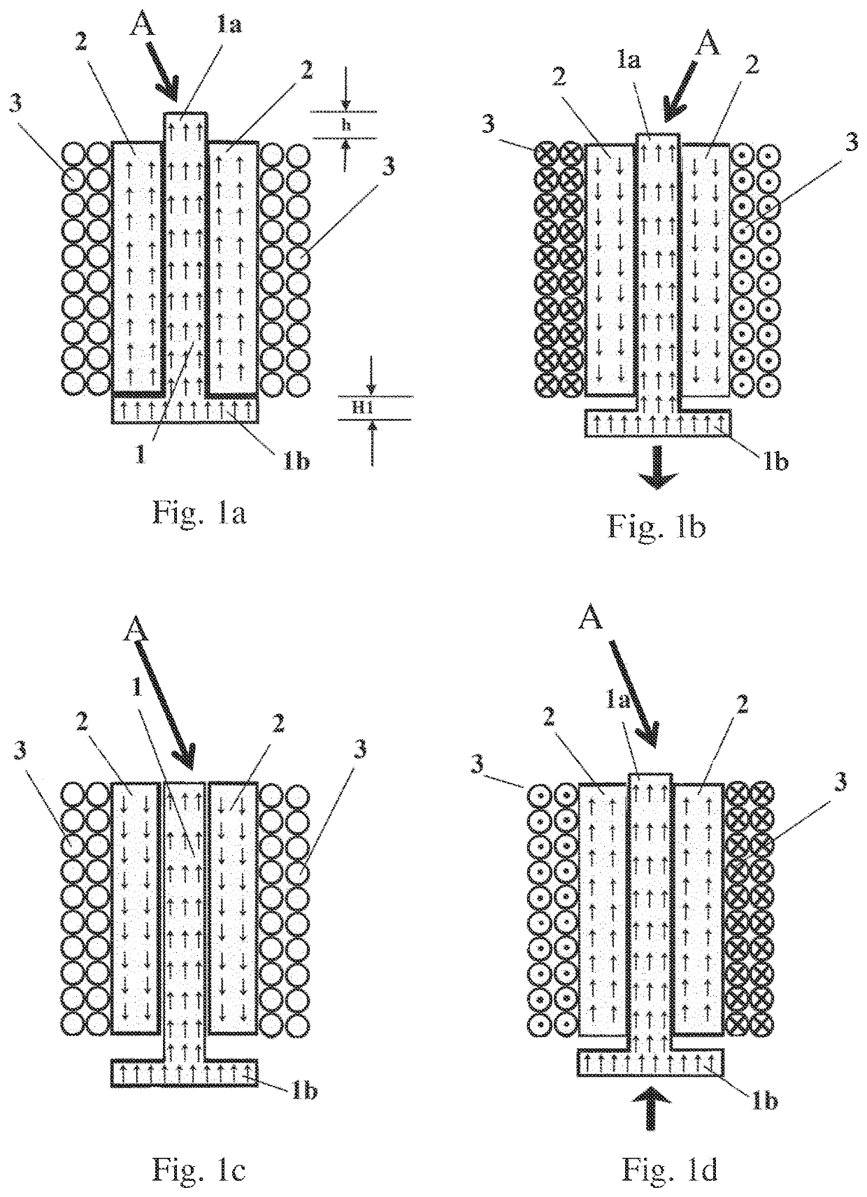
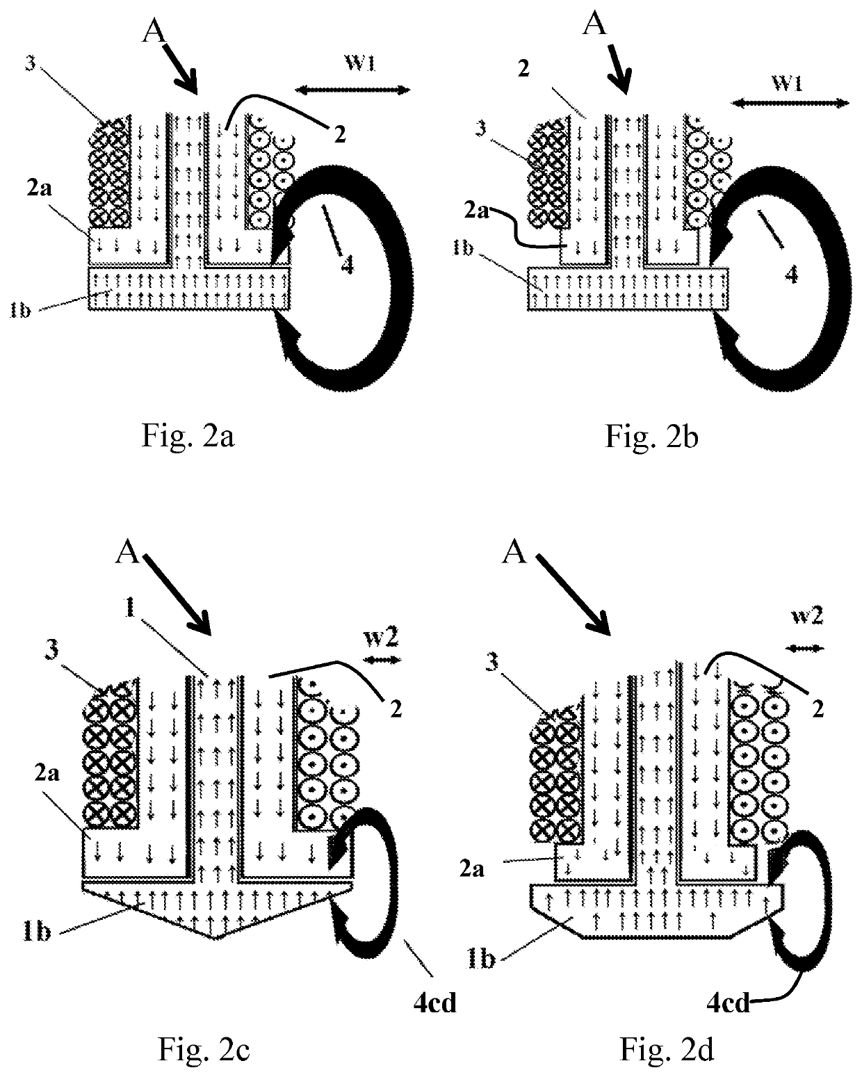
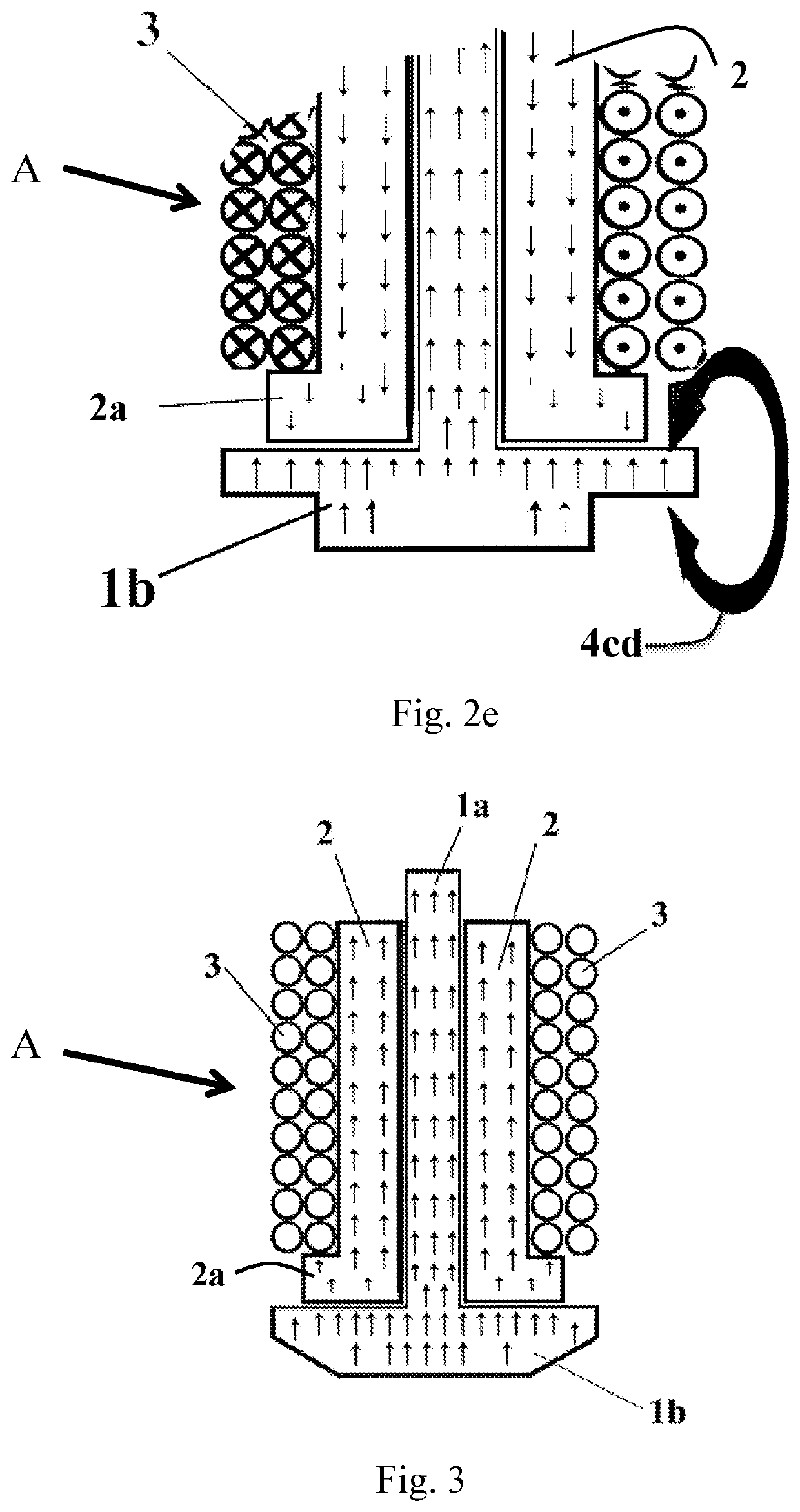
[0084]To clarify the purely magnetic function a view of a magnetically bistable axially symmetrical linear actuator A according to the invention (as part of the display 54 according to the invention) in FIG. 1a the “top” position of the rod 1 is shown. In the case of this and the following representations (see FIG. 1b, FIG. 1c, FIG. 1d) only a rectangular cross-section of the axially symmetrical poles is used for the sake of clarity. The linear, freely movable hard magnetic bar 1 slides in the likewise hard magnetic sleeve 2.

[0085]The stable “top” position in which the coil 3 is not supplied with current is shown. The plate-shaped main pole 1b ensures the spatially clearly defined “upward” position of the rod 1 which is maintained with maximum force. The thickness of the main pole 1b is designated by “H1”. The projection of the auxiliary pole 1a is designated by “h” as the difference in length of the sleeve 2. The axial magnetization directions present in both materials are indicate...


PUM


Abstract

The invention lies in the field of tactile displays and optical-tactile seeing aids. In order, proceeding from the known tactile displays having linear magnetic actuators, to provide such an electromagnetic actuator for tactile applications, in particular for tactile pins in Braille script displays and graphical surface displays, by means of which electromagnetic actuator an inexpensive bistable electromagnetic linear drive unit of simple mechanical design can be realized, the bar of the actuator consists of a material having very high coercivity, i.e. the polarity thereof cannot be changed, the bar being axially enclosed by a hard magnetic sleeve having at most the same length and having considerably lower coercivity, i.e. the polarity thereof can be changed, and the bar being freely movable in the axial direction and the actuation distance of the bar being defined by the excess length of the bar in comparison with the length of the hard magnetic sleeve, such that an auxiliary pole is formed at one end of the bar and a planar main pole is formed at the opposite end.

Description

BACKGROUND OF INVENTIONField of Invention[0001]The invention relates to a magnetically bistable axially symmetrical linear actuator. The invention further relates to devices with the same for tactile display applications, and a switching matrix for controlling coils connected in rows and columns in such a device. Finally, the invention relates to an intuitively usable optically tactile visual aid for substitution of human sight.Brief Description of Related Art[0002]Tactile displays (braille lines) for outputting the data from computers (pcs) for visually impaired people have long been known. With the introduction of graphical user interfaces (e.g. “windows” operating system) pcs and with the growing distribution of screen-oriented operating systems and graphical user software, on the part of the visually impaired the call for novel graphic displays on a tactile basis. Here, for example, a matrix of 200×400 tactile pins is provided on a scanning surface comparable to DIN a4. It is th...

Claims


Application Information

Patent Timeline
Patent Type & Authority Patents(United States)
IPC IPC(8): G09B21/00G09F9/37
CPCG09B21/004G09B21/001G09B21/003G09F9/375G06F3/016
Inventor GREINER, LUITPOLD
Owner GREINER LUITPOLD
Why Eureka
Try Eureka