Converting a symmetrical input signal of a magnetic resonance arrangement into an asymmetrical output signal

a magnetic resonance arrangement and input signal technology, applied in the direction of impedence networks, multiple-port networks, electrical apparatus, etc., can solve the problems of ferrite failure in magnetic fields, relatively expensive and difficult production, etc., to facilitate the use of circuit and method in magnetic resonance arrangements, simple and cost-effective arrangement, and wide bandwidth

Active Publication Date: 2018-03-20
SIEMENS HEALTHCARE GMBH
View PDF9 Cites 0 Cited by
  • Summary
  • Abstract
  • Description
  • Claims
  • Application Information

AI Technical Summary

Benefits of technology

[0013]The first conduction path has two high-pass elements. Each high-pass element acts as a discrete high-pass conduction element and shifts the phase of the signal forward as a result. In contrast, the second conduction path has two low-pass elements. Each low-pass element acts as a discrete low-pass conduction element and shifts the phase of the signal backward as a result. The sum of the phase shift for each conduction path is approximately + / −90°. Dividing the phase shift among two or more stages (e.g., two) achieves a wider bandwidth with simple components. The sum of the phase shift for each conduction path depends on the respective frequency of the signal. Depending on the frequency, the phase shift achieved is somewhat below + / −90° or somewhat above + / −90°. In other words, the phase shift approaches + / −90°. The sum of the phase shift may be +90° or −90° for each conduction path.
[0019]The advantage of converting the symmetrical signals from a digital / analog converter (DAC) into asymmetrical signals by a simple and cost-effective arrangement of known circuit elements is provided. The circuit and method provided herein further provide the advantage of a ferrite-free arrangement, facilitating use of the circuit and method in magnetic resonance arrangements.
[0020]The first conduction path and the second conduction path have a second stage and a high-pass element that is assigned to the second stage and is arranged in a chain with the high-pass element assigned to the first stage. The second conduction path has a low-pass element that is assigned to the second stage and is arranged in a chain with the low-pass element assigned to the first stage. A wider bandwidth is achieved in the fields of application mentioned. A higher filter order is also achieved, enabling a stronger selection.
[0022]In each stage, the phase of a signal is shifted forward (e.g., in the leading direction) by a particular magnitude in the first conduction path. The phase of the signal is shifted backward (e.g., in the lagging direction) by a particular magnitude in the second conduction path. A degree of freedom is thus provided when dimensioning the circuit, allowing optimization of the requirements of the unbalancing process.
[0023]In this case, the first and second stages and / or the third stage of the first and second conduction paths form a two-stage or three-stage Boucherot bridge. A bandwidth is increased with each stage of the Boucherot bridge, making it possible to provide an MRI arrangement that is simultaneously suitable for multiple different field strengths.
[0029]As explained above, each further stage increases the bandwidth. In addition, however, a bandpass filter effect that exists, for example, on account of the properties when using a Boucherot bridge is also enhanced with an increasing number of stages. This results in a degree of freedom that may be used to filter alias frequencies (i.e., alias frequency bands) in the field of application of magnetic resonance, for example.

Problems solved by technology

Ferrites fail in magnetic fields (e.g., in the patient area of an MRI system) since ferrites saturate.
Such components are not usually customary on the market but are made to order and are therefore relatively expensive and difficult to produce.

Method used


Image

  • Converting a symmetrical input signal of a magnetic resonance arrangement into an asymmetrical output signal
  • Converting a symmetrical input signal of a magnetic resonance arrangement into an asymmetrical output signal
  • Converting a symmetrical input signal of a magnetic resonance arrangement into an asymmetrical output signal

Examples


exemplary embodiment 200

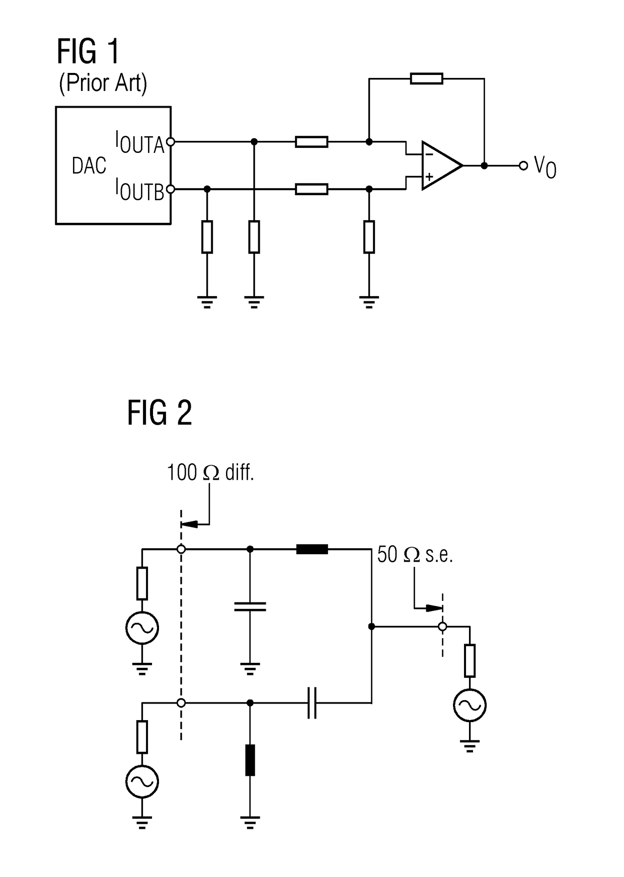
[0048]FIG. 2 is a schematic circuit diagram of an exemplary embodiment 200 of an arrangement for converting a symmetrical signal into an asymmetrical signal using a simple Boucherot bridge. In comparison with the operational amplifier with resistive feedback shown in FIG. 1, the FIG. 2 arrangement has the advantage, inter alia, of better noise properties. The FIG. 2 arrangement takes into account the very high signal dynamics in magnetic resonance arrangements by providing that the noise figure of the components to be used cannot significantly contribute to the total signal-to-noise ratio (SNR).

[0049]The structure and the effect of the circuit are as follows.

[0050]Port 1201 produced by the parallel circuit is used as the output in this embodiment, and two other ports 2202 and 3203 are used as the input. On account of the purely passive structure, signals may also flow in the opposite direction, with the result that the terms “input” and “output” and the functions associated therewit...

exemplary embodiment 400

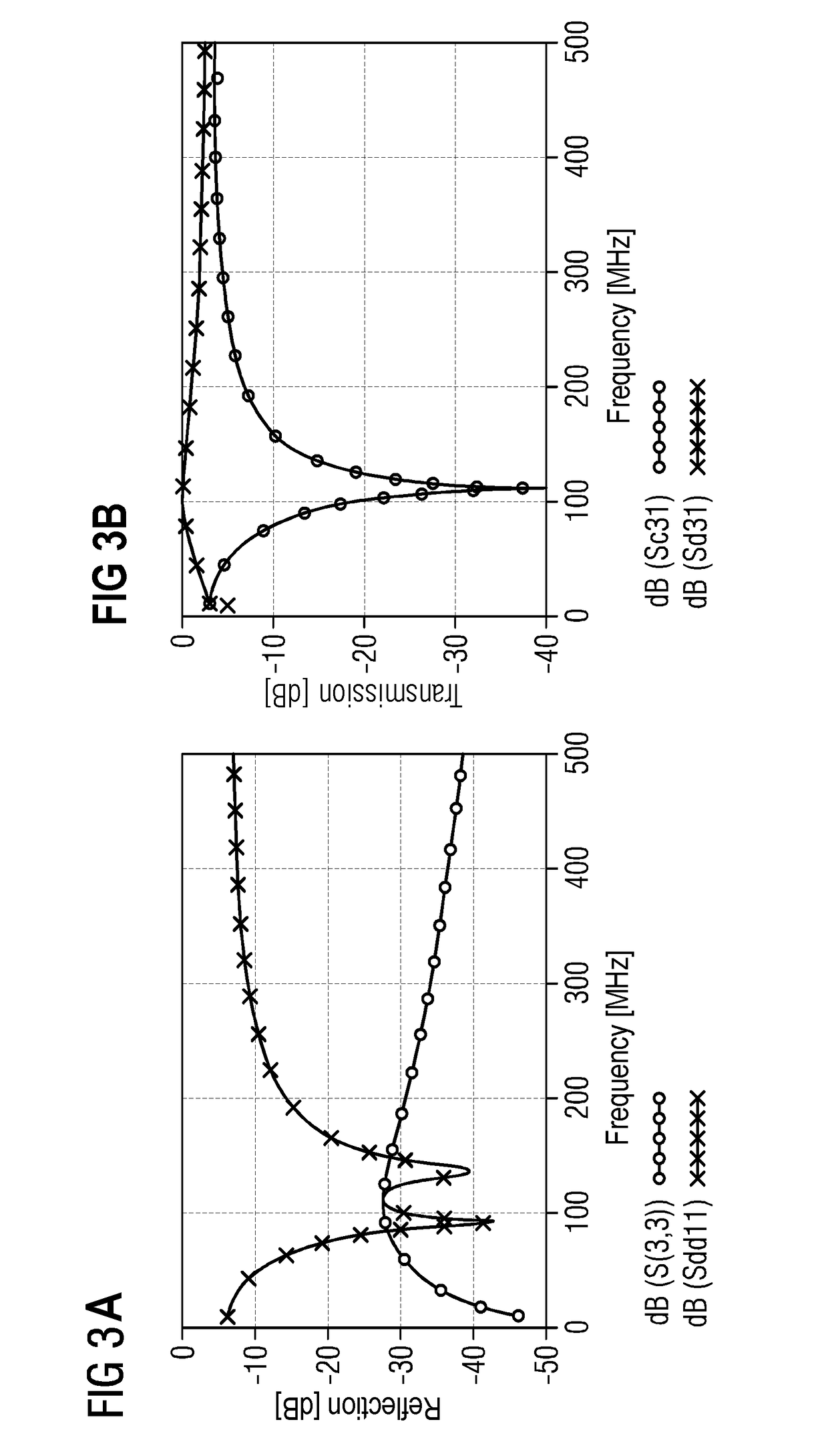
[0058]FIG. 6 is a schematic circuit diagram of a third exemplary embodiment 400 for converting a symmetrical signal into an asymmetrical signal using a three-stage Boucherot bridge. An advantage of this configuration is that further field strengths may be taken into account therewith since the bandwidth increases with each stage. However, a bandpass filter effect that is inherent in the Boucherot bridge also increases. Therefore, embodiments with additional stages are also provided for applications in which further deterioration in the common mode rejection is permissible. However, a balanced ratio prevails in this respect in the circuit shown and allows this three-stage Boucherot bridge to achieve an optimum performance without additional connection.

[0059]In this respect, FIG. 7A-FIG. 7B depict graphs of the signal profile of the S parameters of the arrangement from FIG. 6. As illustrated, the bandwidth is increased both in the transmission (FIG. 7B) and in the reflection (FIG. 7A)...

exemplary embodiment 500

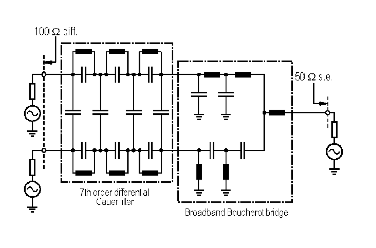
[0060]In order to avoid this disadvantage, for example, the two-stage circuit 300 shown in FIG. 4, as well as the other stage embodiments 200 and 400 described above, may be optimized with the aid of a BPF in the form of a Cauer filter, of the seventh order in the example. This results in the schematic circuit diagram of a fourth exemplary embodiment 500 for converting a symmetrical signal into an asymmetrical signal using a bandpass-optimized two-stage Boucherot bridge, as shown in FIG. 8.

[0061]One of the advantages of bandpass filtering is the filtering of alias bands that may result during operation of the magnetic resonance arrangement. For example, a first alias band is at fmax of 195 MHz for a clock of 160 MHz and a maximum frequency fc of 125 MHz. For the unbalancing in this embodiment, low-pass filtering would be needed at the transmission frequency of fmax and a minimum blocking frequency of 2fc−fmax.

[0062]Filtering of alias bands is advantageously achieved using an upstrea...


PUM


Abstract

A symmetrical input signal is converted into an asymmetrical output signal. A first conduction path and a second conduction path are arranged parallel to one another based on signal flow. The first conduction path and the second conduction path form a first stage and a second stage. The first conduction path includes a first high-pass element assigned to the first stage. The second conduction path includes a first low-pass element assigned to the first stage. The first conduction path and the second conduction path have a second high-pass element assigned to the second stage. The second conduction path includes a second low-pass element assigned to the second stage and arranged in a chain with the first low-pass element. Each high-pass element shifts the phase of a signal forward, and each low-pass element shifts the phase of a signal backward to generate the asymmetrical signal.

Description

CROSS-REFERENCE TO RELATED APPLICATION[0001]This application claims priority under 35 U.S.C §119 to German Patent Application No. 102015200429.5, filed on Jan. 14, 2015, the entire content of which is incorporated herein by reference.FIELD[0002]The present embodiments relate to converting a symmetrical input signal of a magnetic resonance arrangement into an asymmetrical output signal.BACKGROUND[0003]Symmetrical or asymmetrical signals may be transmitted in various circuits. In this case, symmetrical signals are also understood as being “differential” or “balanced to ground” signals. Asymmetrical signals are also called “single ended” or “unbalanced to ground” signals.[0004]For symmetrical signal routing, each conductor is assigned a second conductor of the same design (e.g., the two conductors occur in pairs and may be twisted with one another). The signals have a phase difference of 180°. Interference caused by radio signals or magnetic fields may then have virtually the same effe...

Claims


Application Information

Patent Timeline
Patent Type & Authority Patents(United States)
IPC IPC(8): H03H7/46H03H7/18H03H7/06H03H7/42
CPCH03H7/18H03H7/42H03H7/06
Inventor SEWIOLO, BENJAMIN
Owner SIEMENS HEALTHCARE GMBH
Why Eureka
Try Eureka