
Biocompatible packaging for long term implantable sensors and electronics

a technology of applied in the field of biocompatible packaging for long-term implantable sensors and electronics, can solve the problems of corroding components of implanted medical devices, affecting and affecting the monitoring ability of medical conditions, so as to facilitate the diagnosis of medical conditions

Active Publication Date: 2022-04-05
CALIFORNIA INST OF TECH
View PDF85 Cites 0 Cited by
  • Summary
  • Abstract
  • Description
  • Claims
  • Application Information

AI Technical Summary

Benefits of technology

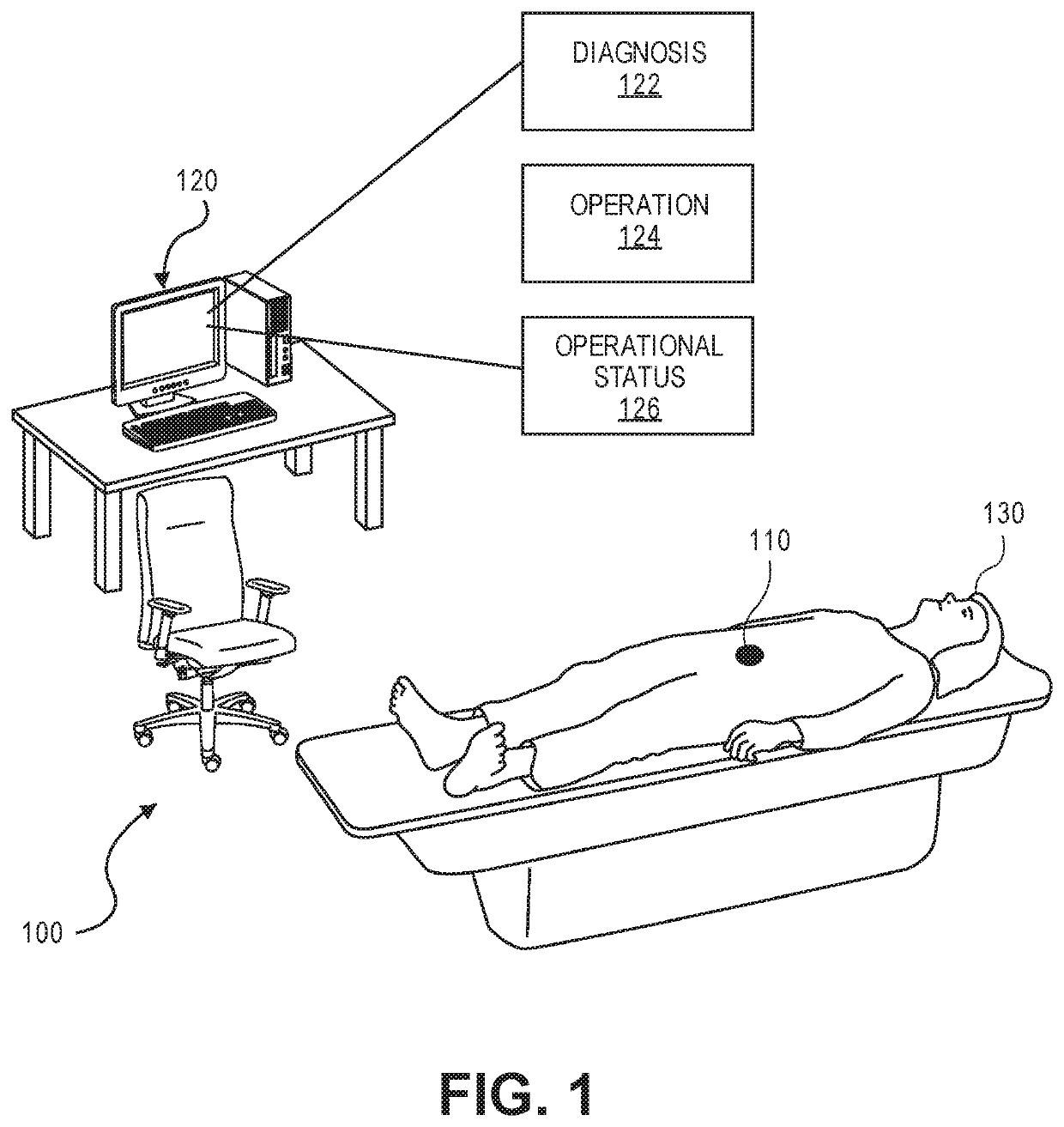
The patent describes a medical system that includes an implantable medical device and a computer. The device collects data and sends it to the computer for analysis. The computer uses this data to diagnose medical conditions, control the device, and track its status. Overall, this system helps to improve the accuracy and effectiveness of medical procedures.

Problems solved by technology

For example, agents of the internal environment, such as fluids, can corrode components of the implanted medical device.
The corrosion degrades the capability for monitoring a medical condition or effectuation a medical operation.
That is because the amount of change indicates a failure in properly sensing the data.
Although telemetric techniques exist for some applications, none provides adequate precision and accuracy for that long time period unless the pressure sensor is properly packaged.
For instance, other than the CardioMEMS® sensor, no pressure sensor is known to have lasted operationally more than one month inside the body due to a variety of reasons ranging from electronics failure to sensitivity and offset drift.
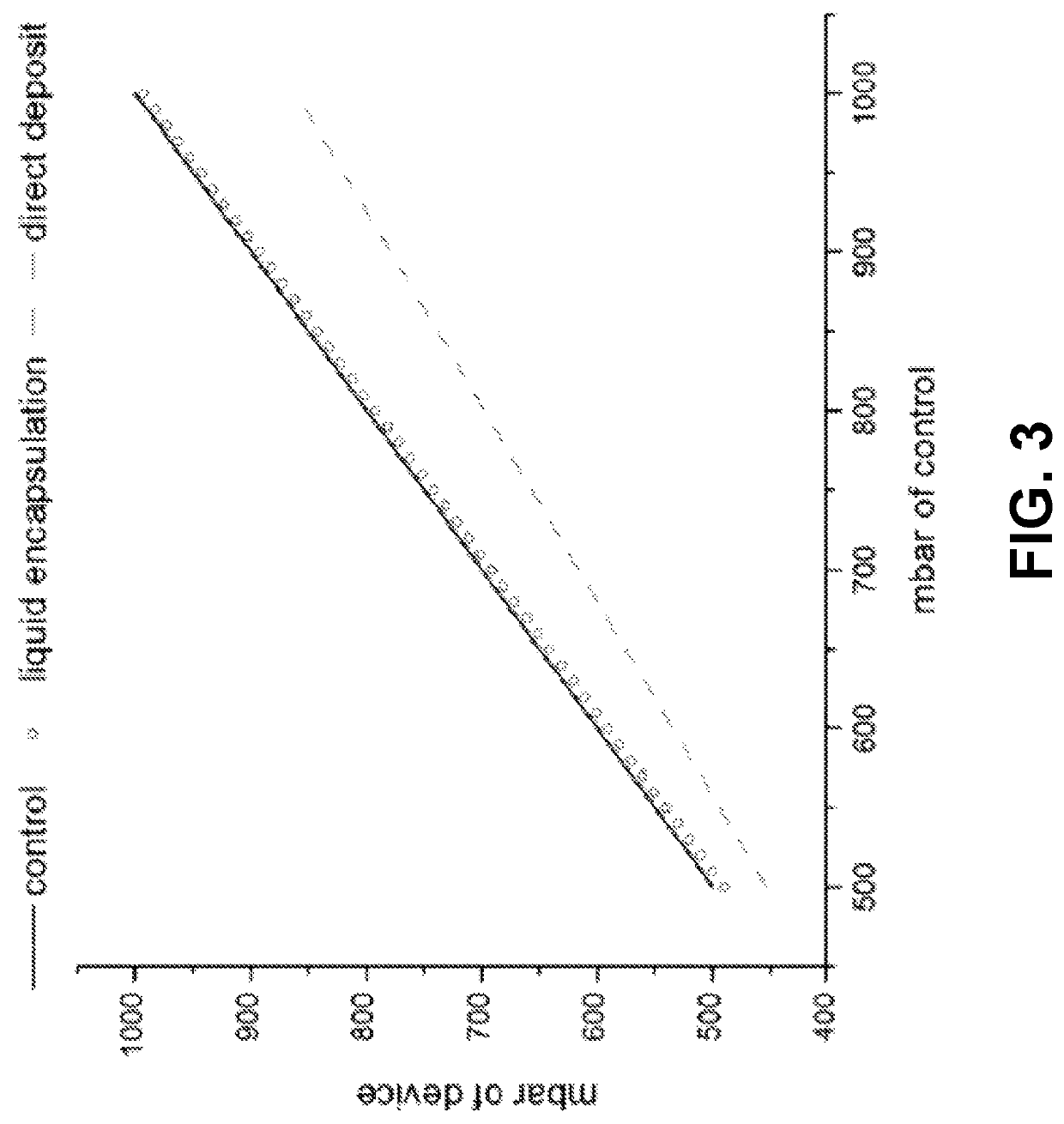
Other encapsulation methods, such as direct deposit of a protective layer on a pressure sensor, can substantially degrade the performance.
Multiple environmental conditions lead to the sensing failure.
For example, corrosion of electrical components of the pressure sensor lead to the sensing failures.
In addition, biofouling negatively impacts the sensitivity and offset drift of the pressure sensor.
The device “Oil+24.92 μm PA-D” showed instability in getting a signal in the third week when it was noticed that the wires used to investigate the device had fallen under the saline leading to corrosion.
These wires may not be present in a final device so they were not submerged, yet by the fourth week, a stable signal was not obtainable.
So, it was deemed that the electronics failed for this reason.
However the device “˜13.17 μm PA-D 1” may have suffered delamination by the fifth week at the membrane, consistent with the observation of sensitivity climbing to about “1” and then the signal becoming unstable and unobtainable the next week even though the wires were never submerged.
There can be situations where it is hard to discern whether a change in the pressure reading is due to sensitivity drift or actual change in pressure.
For this reason, multiple recalibrations and / or schemes to eliminate biofouling may not achieve this tight tolerance.
The increased surface area may also reduce the sensitivity drift from biofouling.

Method used


Image

  • Biocompatible packaging for long term implantable sensors and electronics
  • Biocompatible packaging for long term implantable sensors and electronics
  • Biocompatible packaging for long term implantable sensors and electronics

Examples


Embodiment Construction

[0026]Specific details of various exemplary embodiments of the present invention are set forth in the following description and are illustrated in the figures. Certain well-known technology details, such as methods, apparatus, or systems that would be known by one of ordinary skill, are not set forth in the following description or in the figures to avoid unnecessarily obscuring the various examples. Those of ordinary skill in the relevant art will understand that they can practice other examples of the disclosed subject matter without departing from the scope and spirit of the present invention.

[0027]Embodiments for packaging an implantable medical device are described. Embodiments for methods of manufacturing such a packaged, implantable medical device are described. In addition, embodiments for a medical system that includes a packaged, implantable medical device are described.

[0028]Generally, an implantable medical device represents a medical device suitable for or capable of be...


PUM

PropertyMeasurementUnit
thicknessaaaaaaaaaa
thicknessaaaaaaaaaa
kinematic viscosityaaaaaaaaaa

Abstract

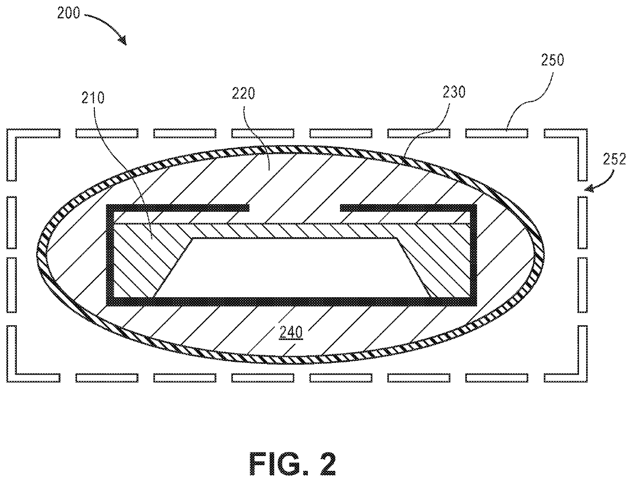
An implantable medical device is described. In an example, the implantable medical device includes an electromechanical substrate and sensor, such as a pressure sensor, disposed on the substrate. At least a portion of the sensor is packaged via a liquid encapsulation. The packaging includes a shaped flexible outer membrane that surrounds at least the portion of the sensor. The packaging also includes a hydrophobic liquid disposed between at least the portion of the pressure sensor and the flexible outer membrane. The implantable medical device can be a part of a medical system used for monitoring medical conditions or performing medical operations based on the implantable medical device. Additionally, manufacturing methods are described for packaging the sensor in a liquid encapsulation.

Description

CROSS-REFERENCES TO RELATED APPLICATIONS[0001]This application claims the benefit of U.S. Provisional Patent Application No. 62 / 140,571, filed Mar. 31, 2015, which is hereby incorporated by reference in its entirety for all purposes.STATEMENT AS TO RIGHTS TO INVENTIONS MADE UNDER FEDERALLY SPONSORED RESEARCH AND DEVELOPMENT[0002]NOT APPLICABLEBACKGROUND[0003]Implantable medical devices are used for a wide range of medical applications. Some of the applications relate to monitoring medical conditions. Other applications relate to proactively or reactively effectuating particular medical operations.[0004]Generally, an implantable medical device has a small form factor to support implantation in a subject, such as a human patient. In certain medical applications, the implanted medical device resides within an internal environment of the subject (e.g., in proximity of a particular organ within the subject's body) for a period of time. In operation, the implanted medical device is subjec...

Claims


Application Information

Patent Timeline
Patent Type & Authority Patents(United States)
IPC IPC(8): A61B5/03A61B5/0215G01L9/00A61B5/021
CPCA61B5/02156A61B5/0215A61B5/02141A61B5/03G01L9/00A61B2562/0247A61B2562/12A61B2562/162A61B2562/168
Inventor TAI, YU-CHONGLIU, YANGSHAPERO, AUBREY M.
Owner CALIFORNIA INST OF TECH
Learn More