
Method and system for establishing metal interconnection layer capacitance prediction model

a capacitance prediction and interconnection layer technology, applied in the field of semiconductor technology, can solve the problems of high process cost, high process cost, and high process cost, and achieve the effects of reducing resource occupation, high reliability, and shortening the modeling period

Active Publication Date: 2022-03-29
JOULWATT TECH INC LTD
View PDF5 Cites 1 Cited by
  • Summary
  • Abstract
  • Description
  • Claims
  • Application Information

AI Technical Summary

Benefits of technology

This approach significantly reduces the modeling time and resource usage while maintaining high accuracy and reliability, enabling the rapid analysis of capacitance changes with size, voltage, and temperature, and supports the design of MOM capacitors with high charge / discharge speed, voltage withstand, and low leakage.

Problems solved by technology

Among them, the capacitance value of a MOS capacitor fluctuates greatly with the change of voltage, resulting in more leakage and low withstand voltage; a MIM capacitor needs to add additional mask in the process of use, so the process cost is high.
The whole modeling process is time-consuming and resource consuming, which will slow down the iteration speed of circuit design.
In addition, the conventional PDK (process design kit) usually only provides the MOM capacitance model composed of metals with a smallest metal spacing of the process, which will limit the design of high voltage applications.
At the same time, limited by the current test conditions, it is difficult to obtain accurate data for small MOM capacitors, and therefore, it is difficult to establish the model of small MOM capacitors.

Method used


Image

  • Method and system for establishing metal interconnection layer capacitance prediction model
  • Method and system for establishing metal interconnection layer capacitance prediction model
  • Method and system for establishing metal interconnection layer capacitance prediction model

Examples


Embodiment Construction

[0038]Various embodiments of the present disclosure will be described in more detail below with reference to the accompanying drawings. In the various figures, the same elements are denoted by the same or similar reference numerals. For the sake of clarity, the various parts in the figures are not drawn to scale. In addition, some well-known parts may not be shown. For simplicity, the semiconductor structure obtained after several steps can be described in one diagram.

[0039]When one layer or region is referred to as being “above” or “on” another layer or region in the description of device structure, it can be directly over or on the other layer or region, or other layers or regions may be intervened therebetween. Moreover, if the device is turned over, the layer or region will be “under” or “below” the other layer or region. When one layer is directly on another layer or region, the context will use the description of “A directly on B” or “A on B and adjacent to B”.

[0040]In the pre...


PUM

PropertyMeasurementUnit
capacitanceaaaaaaaaaa
sizesaaaaaaaaaa
sizeaaaaaaaaaa

Abstract

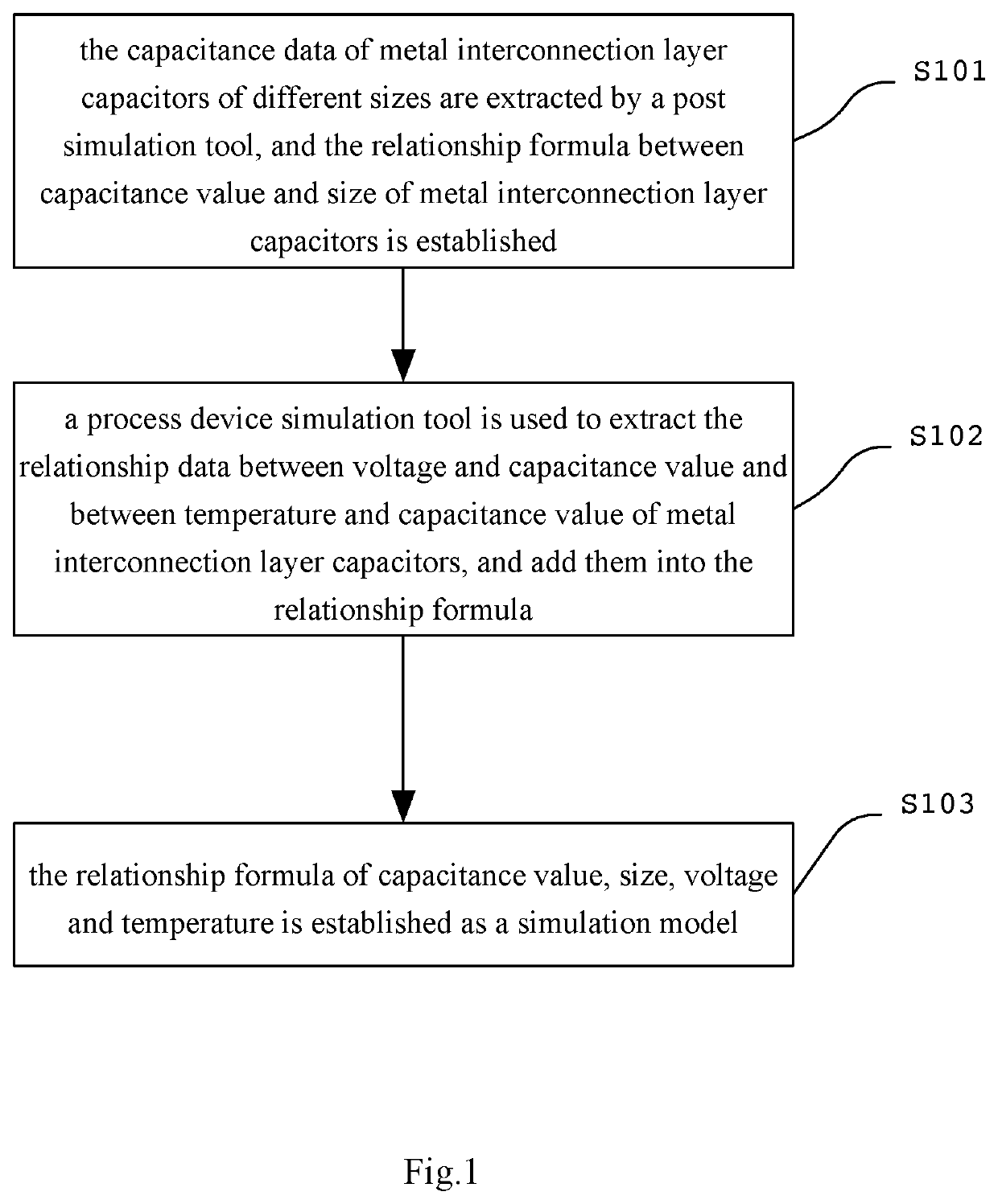
A method and a system for establishing a metal interconnection layer capacitance prediction model are disclosed. The method for establishing the metal interconnection layer capacitance prediction model includes: extracting capacitance data of metal interconnect layer capacitors of different sizes by using a post simulation tool and establishing a relationship formula between capacitance value and size of the metal interconnect layer capacitors; separately extracting relationship data between voltage and capacitance value of the metal interconnect layer capacitors and between temperature and capacitance value of the metal interconnect layer capacitors by using a process device simulation tool, and add the relationship data to the relationship formula; and establishing a simulation model in accordance with the relationship formula of capacitance value, size, voltage and temperature. The method has improved modeling speed and reduced circuit design cycle. The model thereof can be applied to the analysis of the small size capacitors with reliability.

Description

CROSS-REFERENCE TO RELATED APPLICATION[0001]This application claims the benefit of Chinese Patent Application No. 202010150104.6, filed on Mar. 6, 2020, entitled as ‘METHOD AND SYSTEM FOR ESTABLISHING METAL INTERCONNECTION LAYER CAPACITANCE PREDICTION MODEL’, which is incorporated herein by reference in its entirety.BACKGROUND OF THE DISCLOSUREField of the Disclosure[0002]The disclosure relates to the technical field of semiconductor technology, and more particularly, to a method and a system for establishing a metal interconnection layer capacitance prediction model.Description of the Related Art[0003]Three kinds of common capacitors in integrated circuits are MOM (metal oxide metal) capacitors, MOS (metal oxide semiconductor) capacitors and MIM (metal insulator metal) capacitors. Among them, the capacitance value of a MOS capacitor fluctuates greatly with the change of voltage, resulting in more leakage and low withstand voltage; a MIM capacitor needs to add additional mask in the...

Claims


Application Information

Patent Timeline
Patent Type & Authority Patents(United States)
IPC IPC(8): G06F30/367G06F119/06H01L23/522
CPCG06F30/367G06F2119/06H01L23/5223G06F30/36G06F30/39
Inventor JIANG, SHENGFENGLU, YANG
Owner JOULWATT TECH INC LTD
Learn More