Apparatus, method for determining state of sample, and analysis system
a sample and apparatus technology, applied in the field of apparatus, can solve the problems of increasing the amount of sample and the inability to draw in a sufficient amount of sample by suction, and achieve the effect of reducing analysis accuracy and analysis efficiency
- Summary
- Abstract
- Description
- Claims
- Application Information
AI Technical Summary
Benefits of technology
Problems solved by technology
Method used
Image
Examples
example 1
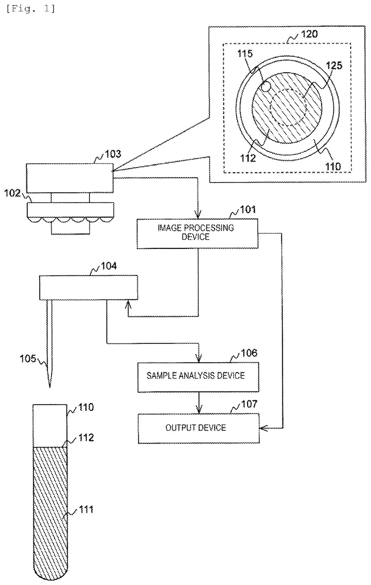
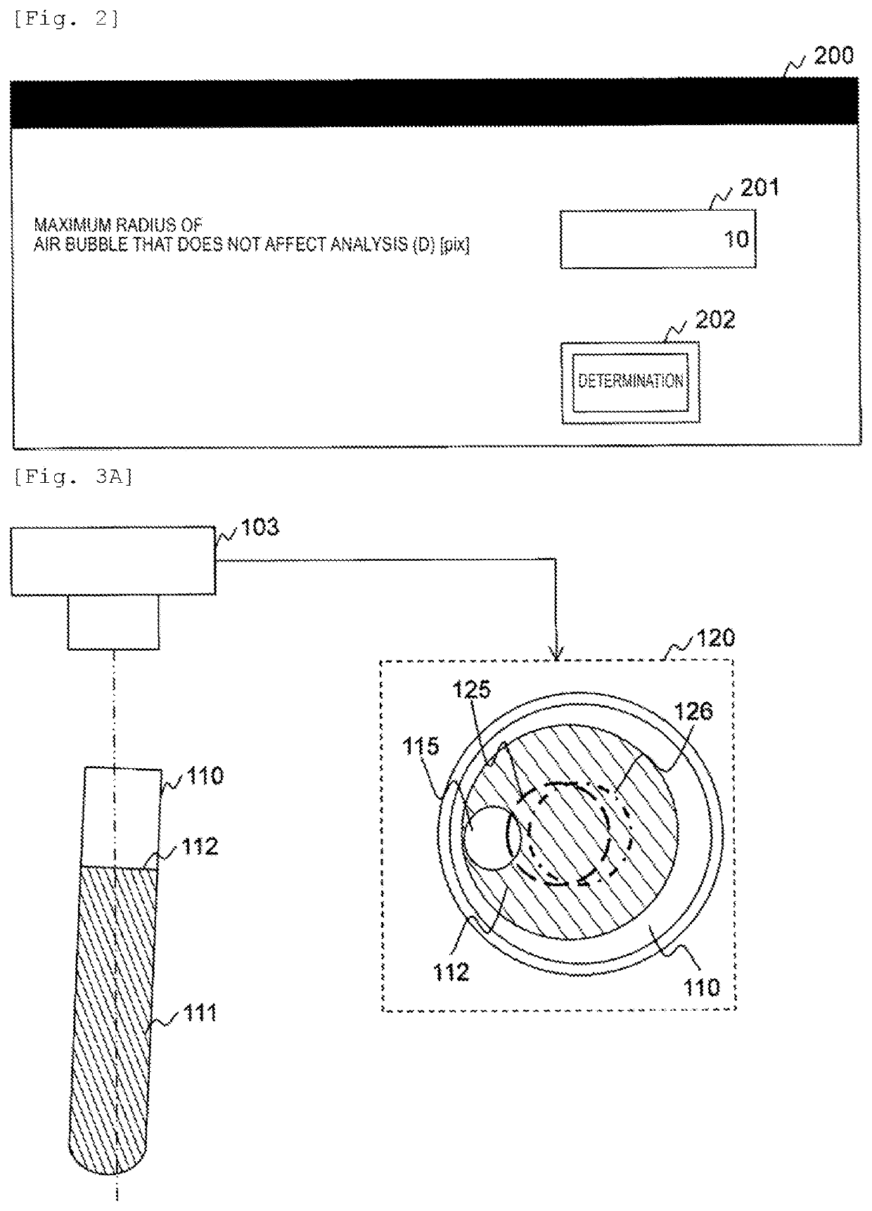
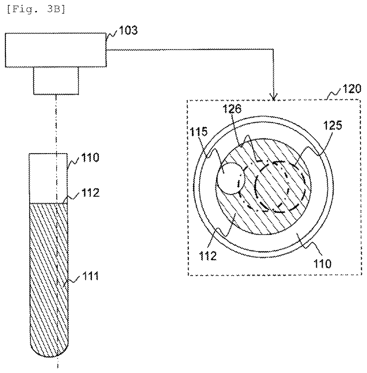
[0038]In Example 1, a device that executes an image process of determining a state of a sample surface from a position and a size of an object to be detected (such as air bubbles) with respect to a detection range set in an image of the sample surface obtained by imaging a sample surface in a container on the basis of the image, and a system including the device will be described.
[0039]FIG. 1 is a view illustrating a configuration example of an automatic analysis system according to Example 1.
[0040]The automatic analysis system includes an image processing device 101, a lighting device 102, an image acquisition device 103, a sample acquisition device 104, a sample analysis device 106, and an output device 107, and also includes a device that installs a container 110 in which a sample 111 is contained.
[0041]The sample 111 is a sample to be analyzed such as blood or urine. A sample surface 112 is a liquid level of the sample 111. The container 110 is a container such as a test tube fo...
example 2
[0147]In Example 2, the image processing device 101 corrects the image input from the image acquisition device 103 and executes similar processes to those in Example 1 using the corrected image. Example 2 will be described hereinafter while mainly referring to differences from Example 1.
[0148]A system configuration according to Example 2 is identical to that according to Example 1. A hardware configuration of the image processing device 101 according to Example 2 is identical to that of the image processing device 101 according to Example 1. A software configuration of the image processing device 101 according to Example 2 partially differs from that according to Example 1. FIG. 10 is a view illustrating an example of the software configuration of the image processing device 101 according to Example 2.
[0149]Example 2 differs from Example 1 in that a program that realizes an image correction portion 1001 is stored in the storage device 402. Example 2 also differs from Example 1 in th...
example 3
[0163]Example 3 differs from Example 1 in that coefficients are updated either periodically or successively using an image acquired at the time of analysis as a new learning image. Example 3 will be described hereinafter while mainly referring to differences from Example 1.
[0164]A system configuration according to Example 3 is identical to that according to Example 1. A hardware configuration of the image processing device 101 according to Example 3 is identical to that of the image processing device 101 according to Example 1. A software configuration of the image processing device 101 according to Example 3 partially differs from that according to Example 1. FIG. 13 is a view illustrating an example of the software configuration of the image processing device 101 according to Example 3. FIG. 14 is a view illustrating an example of a GUI displayed by the image processing device 101 according to Example 3.
[0165]Example 3 differs from Example 1 in that programs that realize a user op...
PUM
 Abstract
Description
Claims
Application Information
 - R&D
- Intellectual Property
- Life Sciences
- Materials
- Tech Scout
- Unparalleled Data Quality
- Higher Quality Content
- 60% Fewer Hallucinations
Browse by: Latest US Patents, China's latest patents, Technical Efficacy Thesaurus, Application Domain, Technology Topic, Popular Technical Reports.
© 2025 PatSnap. All rights reserved.Legal|Privacy policy|Modern Slavery Act Transparency Statement|Sitemap|About US| Contact US: help@patsnap.com


